For Audi A6 (C6), Audi S6 2004, 2005, 2006, 2007, 2008, 2009, 2010, 2011 model year.
Cigarette lighter fuse (front) – (fuse box in passenger compartment (right side, fuse №2/20A) Cigarette lighter fuse (rear) – (fuse box in luggage compartment, fuse №16/20A) |
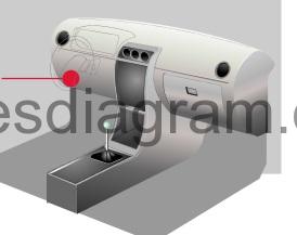
fuse box location.
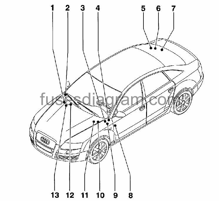
Location No. | Description |
1 | |
2 | |
3 | Fuses on steering cross member (not used) |
4 | Fuses on Vehicle Electrical System Control Module |
5 | Fuses (SF) on Fuse Holder F |
6 | |
7 | |
8 | |
9 | |
10 | Fuses (SA) on Fuse Holder A |
11 | |
12 | Fuses on Connector Station on A-pillar, right lower |
13 |
Fuse box in engine compartment.
Fuses in E-Box plenum chamber, right.
fuse box layout.
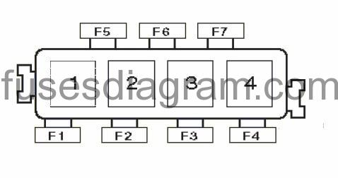
1 |
|
2 | Suspension compressor motor relay |
3 | Secondary Air Injection (AIR) Pump Relay /Diesel: Glow plug relay |
4 |
|
F1 |
|
F2 | (50A) Petrol: Secondary air injection (AIR) system |
F3 | (40A) Self-levelling suspension |
F4 | (15A) Petrol: Engine coolant blower motor |
F5 |
|
F6 |
|
F7 |
|
Fuses in E-Box plenum chamber, left.
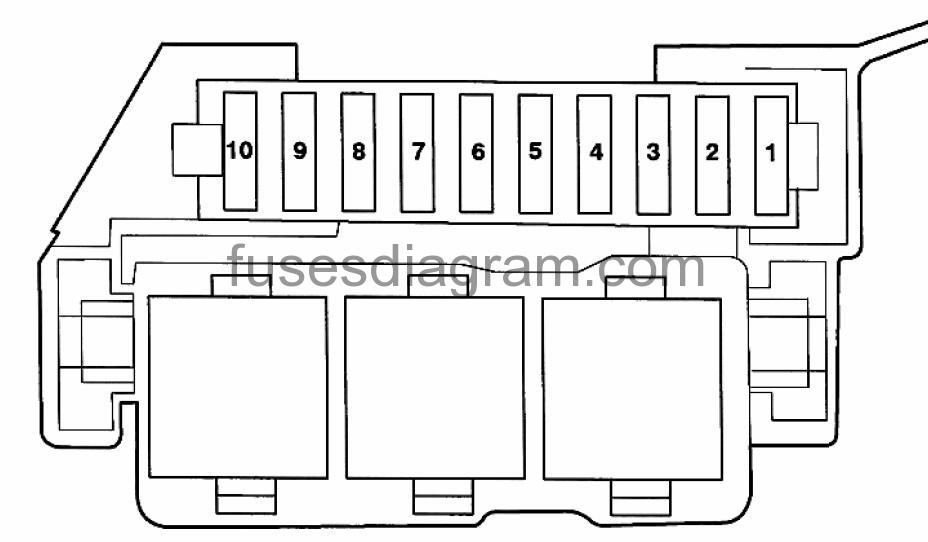
legend (model year 2005-2006)
Fuse No. | Rating (A) | Description |
1 | 15A | Brake Booster Relay |
2 | 20F 30A | Ignition Coils (BKH) gnition Coils (bNk) |
3 | 10A 15A | Coolant Circulation Pump relay (BNK) Aux Engine Coolant (EC) Pump Relay (BKH) Camshaft Adjustment Valve 1 Camshaft Adjustment Valve 2 Camshaft Adjustment Valve 1 (exhaust) (BKH) Camshaft Adjustment Valve 2 (exhaust) (BKH) Map Controlled Engine Cooling Thermostat (BXA) ntake Flap Motor (BXA) Variable Intake Manifold Runner Motor (BXA) |
4 | 15A | Engine Control Module (ECM) Engine Control Module (ECM) Fuel Injectors (BNK, BKH) |
5
| 15A
| Mass Air Flow (MAF) Sensor (BNK) Secondary Air Injection (AIR) Pump Relay (BNK) Evaporative Emission (EVAP) Canister Purge Regulator Valve Secondary Air Injection (AIR) Solenoid Valve (BNK) Left Electro-Hydraulic Engine Mount Solenoid Valve Right Electro-Hydraulic Engine Mount Solenoid Valve Intake Manifold Tuning (IMT) Valve Intake Air Switch-Over Valve
|
6 | 15A | Oxygen Sensor (O2S) Heater Oxygen Sensor (O2S) 2 Heater |
7 | 15A | Oxygen Sensor (O2S) 1 (behind Three Way Catalytic Converter (TWC)) Heater Oxygen Sensor (O2S) 2 (behind Three Way Catalytic Converter (TWC)) Heater |
8 | 5A | Engine Control Module (ECM) |
9 | 5A | Coolant Fan |
10 | 10A | Transmission Control Module (TCM) |
Legend (model year 2007-2008).
Fuse No. | Rating (A) | Description |
1 | 15A | Brake Booster Relay |
2 | 30A 20A | Ignition Coils (BKH) Ignition Coils (BNK, BXA) |
3 | 10A | Coolant Circulation Pump relay (BNK) Aux Engine Coolant (EC) Pump Relay (BKH) Camshaft Adjustment Valve 1 Camshaft Adjustment Valve 2 Camshaft Adjustment Valve 1 (exhaust) (BKH) Camshaft Adjustment Valve 2 (exhaust) Map Controlled Engine Cooling Thermostat (BXA) Intake Flap Motor (BXA) Variable Intake Manifold Runner Motor (BXA) |
4 | 15A | Engine Control Module (ECM) Engine Control Module (eCm) Fuel Injectors (BNK, BKH) |
5 | 15A | Mass Air Flow (MAF) Sensor (BNK) Secondary Air Injection (AIR) Pump Relay (BNK) Evaporative Emission (EVAP) Canister Purge Regulator Valve Secondary Air Injection (AIR) Solenoid Valve (BNK) Left Electro-Hydraulic Engine Mount Solenoid Valve Right Electro-Hydraulic Engine Mount Solenoid Valve Intake Manifold Tuning (IMT) Valve Intake Air Switch-Over Valve Intake Manifold Runner Control (IMRC) Valve (BKH) Fuel Metering Valve (BKH) Leak Detection Pump (LDP) |
6 | 15A | Oxygen Sensor (O2S) Heater Oxygen Sensor (O2S) 2 Heater |
7 | 15A | Oxygen Sensor (O2S) 1 (behind Three Way Catalytic Converter (TWC)) Heater Oxygen Sensor (O2S) 2 (behind Three Way Catalytic Converter (TWC)) Heater |
8 | 5A | Engine Control Module (ECM) |
9 | 5A | Coolant Fan |
10 | 10A | Transmission Control Module (TCM) |
Legend (2009-).
Fuse No. | Rating (A) | Description |
1 | 15A | Brake Booster Relay |
2 | 30A 20A | N… – Ignition Coils (BKH) N… – Ignition Coils (bVJ, BXA) |
3 | 10A 15A | Coolant Circulation Pump relay Aux Engine Coolant (EC) Pump Relay (CAJA) Left Electro-Hydraulic Engine Mount Solenoid Valve (CAjA) Right Electro-Hydraulic Engine Mount Solenoid Valve (CAJA) Intake Manifold Tuning (IMT) Valve Camshaft Adjustment Valve 1 Camshaft Adjustment Valve 2 Intake Manifold Tuning (IMT) Valve 2 Camshaft Adjustment Valve 1 (exhaust) Camshaft Adjustment Valve 2 (exhaust) Map Controlled Engine Cooling Thermostat Intake Flap Motor (BXA) |
|
| Variable Intake Manifold Runner Motor (BXA) Charge Air Cooling Pump (CAJA) |
4 | 15A | Engine Control Module (ECM) Engine Control Module (eCm) 2 |
5 | 15A | Mass Air Flow (MAF) Sensor Mass Air Flow (MAF) Sensor 2 (BXA) Secondary Air Injection (AIR) Pump Relay Evaporative Emission (EVAP) Canister Purge Regulator Valve Secondary Air Injection (AIR) Solenoid Valve Left Electro-Hydraulic Engine Mount Solenoid Valve Right Electro-Hydraulic Engine Mount Solenoid Valve Secondary Air Injection (AIR) Pump Solenoid Valve 2 Intake Air Switch-Over Valve Intake Manifold Runner Control (IMRC) Valve Fuel Metering Valve Fuel Metering Valve 2 Oil Pressure Regulation Valve Leak Detection Pump (LDP) |
6 | 15A | Oxygen Sensor (O2S) Heater Oxygen Sensor (O2S) 2 Heater |
7 | 15A | Oxygen Sensor (O2S) 1 (behind Three Way Catalytic Converter (TWC)) Heater Z30 – Oxygen Sensor (O2S) 2 (behind Three Way Catalytic Converter (TWC)) Heater |
8 | 5A | Engine Control Module (ECM) Engine Control Module (eCm) (BXA) |
9 | 5A | Coolant Fan |
10 | 10A | Transmission Control Module (TCM) |
E-Box Plenum Chamber Relay & Fuse Panel – Left Side.
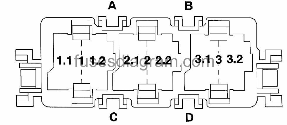
model year 2005-2006.
Relay No. | Description |
1 | Not used |
1.1 | Brake Booster Relay |
1.2 | Coolant Circulation Pump Relay |
2 | Fuel Pump (FP) Relay |
2.1 | Not used |
2.2 | Not used |
3 | Motronic Engine Control Module (ECM) Power Supply Relay |
3.1 | Not used |
3.2 | Not used |
Model Year: 2007 & Up
Relay No. | Description |
1 | Not used |
1.1 | Brake Booster Relay |
1.2 | Coolant Circulation Pump Relay |
2 | Fuel Pump (FP) Relay, Engine Component Power Supply Relay |
2.1 | Not used |
2.2 | Not used |
3 | Motronic Engine Control Module (ECM) Power Supply Relay |
3.1 | Not used |
Fuses on Main Fuse Holder E-Box plenum chamber, right. (audi a6 C6).
fuse box diagram.

Terminal No. | Description | Amp Rating |
1 | Screwed Connection (Terminal 30) | – |
2 | Second Speed Coolant Fan Fuse | 60A |
3 | Coolant Fan Fuse | 60A |
4 | Screwed Connection Battery(+) Cable | – |
5 | Not used | – |
A | Not used | – |
B | Not used | – |
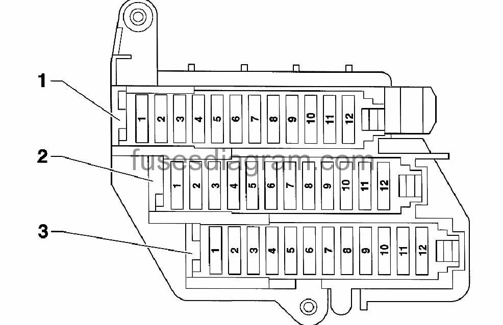
Fuse box in passenger compartment Audi A6 (C6).
Fuses Instrument Panel – Right Side.
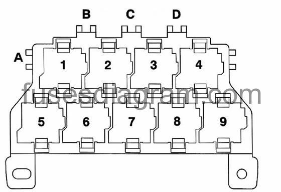
fuse box diagram.
legend (model year 2004-2006)
1 – BLACK FUSE HOLDER
Fuse No. | Rating (A) | Device |
1 | – | – Not used |
2 | 20A | Cigarette lighter (front) |
3 | 5A | Tire pressure monitoring system |
4 | 20A | Electrical outlet front (center console) |
5 | 15A | Intelligent power module passenger (glove box lock) |
6 | 15A | Front right door control module Rear right door control module |
7 | 20A | Sunroof control module |
8 | 10A | Climatronic control module |
9 | 30A | Climatronic control module |
10 | 5A | Front information display control module |
11 | 15A | Level control system control module |
12 | 5A | Media player, position 1 Media player, position 2 |
Fuse No. | Rating (A) | Device |
1 | 20A 30A | Transfer fuel pump (FP) (BNK) Fuel pump (FP) control module (BKH, BVJ, BXA) |
2 | – | – Not used |
3 | – | – Not used |
4 | – | – Not used |
5 | 5A | Lever control system control module |
6 | 5A | Selector lever sensor system control module |
7 | 5A | Acoustic parking system control module |
8 | 5A | Data Bus On Board Diagnostic Interface |
9 | 5A | Automatic headlight range control module |
10 | 5A | Airbag control module Front passenger airbag disabled indicator lamp |
11 | 5A | Left rear heated seat regulating switch Right rear heated seat regulating switch |
12 | – | – Not used |
Fuse No. | Rating (A) | Device |
1 | 15A | Keyless Access Authorization Antenna Reader |
2 | 20A | Cigarette lighter |
3 | 5A | Tire pressure monitoring system |
4 | 20A | Electrical outlet front (center console) |
5 | 15A | Vehicle Electrical System Control Module 2 |
6 | 15A | Front right door control module Rear right door control module |
7 | 20A | Sunroof control module |
8 | 10A | Climatronic control module |
9 | 30A | Climatronic control module Left Front Heated Seat Right Front Heated Seat |
10 | 5A | Front Information Display Control Head Control Module |
11 | – | – Not used |
12 | 5A | Media player, position 1 Media player, position 2 External Audio Source Connection (from 11.2006) |
Fuse No. | Rating (A) | Device |
1 | 20A 30A | Transfer fuel pump (FP) J538 – Fuel pump (FP) control module |
2 | 15A | Level Control System Control Module |
3 | 10A | Directional Stabilization Assistance Control Module |
4 | 5A | Lane Change Assistance Control Module (1) |
5 | 5A | Lever control system control module |
6 | 5A | Selector lever sensor system control module |
7 | 5A | Parking Aid control module |
8 | 5A | Data Bus On Board Diagnostic Interface |
9 | 5A | Headlamp Range Control Module (HLP Rt) Headlamp Range/Cornering Lamp Control Module |
10 | 5A | Airbag control module Front passenger airbag disabled indicator lamp |
11 | 5A | Left rear heated seat regulating switch Right rear heated seat regulating switch |
12 | – | – Not used |
3 – fuse holder ST3 (red).
F1 | (25A) Special vehicle equipment |
F2 | (15A) Special vehicle equipment |
F3 | (15A) Special vehicle equipment |
F4 | (5A/10A) |
F5 | (10A/15A/25A) Special Vehicle equipment |
F6 | (5A/10A/15A) Special Vehicle equipment |
F7 | (5A/10A/25A) |
F8 | (10A/15A/20A) Auxiliary power socket |
F9 | (15A) Special vehicle equipment |
F10 | – |
F11 | – |
F12 | – |
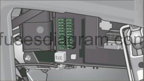
Fuse Panel (SB) On Instrument Panel – Left Side.
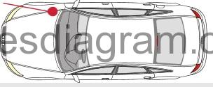
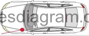
fuse box location.
fuse box layout.
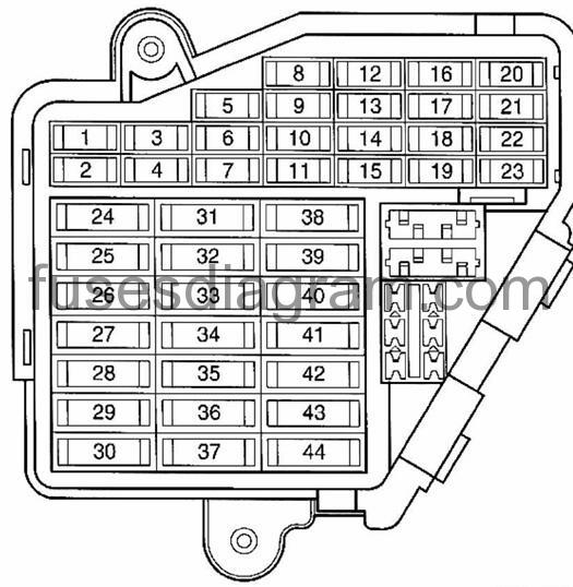
legend (model year 2005-2006).
Fuse No. | Rating (A) | Device |
1 | – | – Not used |
2 | – | – Not used |
3 | 5A | Engine Control Module (ECM) |
4 | 5A | Oil Level Thermal Sensor |
5 | 5A | Air Quality Sensor A/C Pressure/Temperature Sensor |
6 | 5A | ABS Control Module |
7 | 5A | 16 Pin Connector Data Link Connector (DLC) (Below instrument panel, left) |
8 | 5A | Garage Door Opener Control Module |
9 | 5A | Automatic Day/Night Interior Mirror |
10 | 5A | Distance Regulation Control Module |
11 | – | – Not used |
12 | 10A | 6 Pin Connector Data Link Connector (DLC) (Below instrument panel, left) |
13 | 10A | Steering Column Electronic Systems Control Module |
14 | 5A | Brake Light Switch |
15 | 10A | Instrument Cluster Control Module |
16 | 10A | Telephone Transceiver |
17 | 10A | ABS Control Module |
18 | 5A | Head Lamp left and right with Cornering Lamp |
19 | 5A | Rain/Light Recognition Sensor |
20 | 5A | Left Washer Nozzle Heater Right Washer Nozzle Heater |
21 | 5A | Antenna amplifier |
22 | – | – Not used |
23 | 5A | Electro-Mechanical Parking Brake Control Module |
24 | – | – Not used |
25 | – | – Not used |
26 | – | – Not used |
27 | – | – Not used |
28 | – | – Not used |
29 | – | – Not used |
30 | – | – Not used |
31 | 15A | Backup light switch |
32 | 30A | Vehicle Electrical System Control Module |
33 | 25A | Vehicle Electrical System Control Module |
34 | 25A | Vehicle Electrical System Control Module |
35 | – | – Not used |
36 | 30A | Headlamp Washer Relay |
37 | 25A | ABS Control Module |
38 | 30A | Wiper Motor Control Module |
39 | 15A | Driver Door Control Module Left Rear Door Control Module |
40 | 20A | J4 – Horn High Tone Horn Low Tone Horn |
41 | 15A | Fresh Air Blower Control Module |
42 | 30A | Access/Start Authorization Switch Access/Start Control Module |
43 | 15A | Rear Window Wiper Motor |
44 | 15A¹ 35A² | Keyless Access Authorization Antenna Reader (1) Left Rear Window Regulator Motor Driver Window Regulator Motor (2) |
(1) – Model year through 10/2005
(2) – Model year from 11/2005
Some of the equipment items listed are optional or only available on certain model configurations.
legend (model year 2007 & Up).
Fuse No. | Rating (A) | Device |
1 | – | – Not used |
2 | – | – Not used |
3 | 5A | Engine Control Module (ECM) |
4 | 5A | Oil Level Thermal Sensor |
5 | 5A | Air Quality Sensor A/C Pressure/Temperature Sensor |
6 | 5A | ABS Control Module G476 – Clutch Position Sensor |
7 | 5A | 16 Pin Connector Data Link Connector (DLC) (Below instrument panel, left) |
8 | 5A | Garage Door Opener Control Module |
9 | 5A | Automatic Day/Night Interior Mirror |
10 | 5A | Distance Regulation Control Module |
11 | – | – Not used |
12 | 10A | 16 Pin Connector Data Link Connector (DLC) (Below instrument panel, left) |
13 | 10A | Steering Column Electronic Systems Control Module |
14 | 5A | Brake Light Switch (1) |
15 | 10A | Instrument Cluster Control Module Data Bus On Board Diagnostic Interface |
16 | 10A | Telephone Transceiver |
17 | 10A | ABS Control Module |
18 | 5A | Head Lamp left and right with Cornering Lamp Headlamp Range/Cornering Lamp Control Module |
19 | 5A | Rain/Light Recognition Sensor |
20 | 5A | Left Washer Nozzle Heater Right Washer Nozzle Heater |
21 | – | – Not used |
22 | – | – Not used |
23 | 5A | Electro-Mechanical Parking Brake Control Module |
24 | – | – Not used |
25 | – | – Not used |
26 | – | – Not used |
27 | – | – Not used |
28 | – | – Not used |
29 | – | – Not used |
30 | – | – Not used |
31 | 15A | F4 – Backup light switch |
32 | 30A | Vehicle Electrical System Control Module |
33 | 25A | Vehicle Electrical System Control Module |
34 | 25A | Vehicle Electrical System Control Module |
35 | – | Not used |
36 | 30A | Headlamp Washer Relay |
37 | 25A | ABS Control Module |
38 | 30A | Wiper Motor Control Module |
39 | 15A | Driver Door Control Module Left Rear Door Control Module |
40 | 20A | Horn High Tone Horn H7 Low Tone Horn |
41 | 15A | Fresh Air Blower Control Module |
42 | 30A | Access/Start Authorization Switch J518, Access/Start Control Module |
43 | 15A | Rear Window Wiper Motor |
44 | 35A | Left Rear Window Regulator Motor, Driver Window Regulator Motor |
(1) Canceled as from 9/2008.
Fuses and relay Behind Storage Compartment – Driver's Side.
legend (model year 2005-2006)
Fuse Location | Description |
A | ABS Control Module Fuse 1(40A) |
B | Not used |
C | Not used |
D | Not used |
1 | Power Supply Relay (terminal 15) |
2 | Headlamp Washer Relay |
3 | Not used |
4 | Starter Relay |
5 | Power Supply Relay (terminal 75x) (through 04.2005) |
6 | Starter Relay 2 |
7.1 | Horn Relay |
7.2 | Power Supply Relay (terminal 75x) (From 05.2005) |
8 | Not used |
9 | Not used |
legend (model year 2007 & Up)
Fuse Location | Description |
A | ABS Control Module Fuse 1 (40A) |
B | Not used |
C | Driver Power Seat Adjustment Circuit Breaker 1 (30A) |
D | Not used (through 08.2009) Communication Fuse (5A) (from 09.2008) |
E | Not used |
1 | Power Supply Relay (terminal 15) |
2 | Headlamp Washer Relay |
3 | Not used |
4 | Starter Relay |
5 | Not used |
6 | Starter Relay 2 |
7.1 | Horn Relay |
Fuse box in luggage compartment Audi A6 (C6).
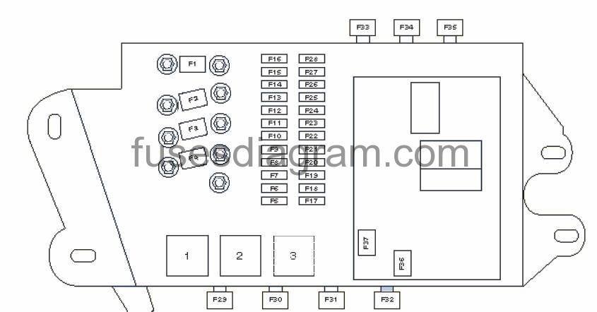
Fuse Panel (SF) Luggage Compartment – Right Side.
fuse box diagram.
1 | Heated rear window relay |
2 | ^2006: Auxiliary heater fuel pump relay |
3 | Fuel pump (FP) relay |
F1 |
|
F2 | (150A) Ignition auxiliary circuits supply voltage |
F3 | (40A/80A) Special vehicle equipment |
F4 |
|
F5 | (20A) ^2006: Auxiliary heater |
F6 | ^2006: Not used |
F7 | (30A) Parking brake control module |
F8 | (30A) Parking brake control module |
F9 | (20A) Auxiliary power socket |
F10 | (5A) Battery control module |
F11 | (20A) Comfort System Central Control Module |
F12 | (5A) ^2006: Alarm system |
F13 | (30A) Comfort System Central Control Module |
F14 | (35A) Right Rear Window Regulator Motor (1) (from 11/2005) V148 – Front Passenger Window Regulator Motor |
F15 | (5A/10A/20A) Parking Aid Control Module |
F16 | (20A) Rear Cigarette lighter |
F17 | ^2006: Not used/ 2007^ – Rear View Camera System Control Module |
F18 | (30A) Tailgate open/close control module, Power Rear Lid Avant (Master) |
F19 | (30A) Tailgate open/close control module, Power Rear Lid Avant (Slave) |
F20 | (20A) Tailgate open/close control module, Door Closing Assist Wagon |
F21 | (5A) ^2006: Audio system/ 2007^ – not used |
F22 | (5A) Television tuner |
F23 | (5A) ^2006: Navigation System with CD Drive Control Module |
F24 | (30A) ^2006:Audio system – Digital Sound System Control Module |
F25 | (5A) ^2008:Audio system – Satellite Radio |
F26 | (15A) Trailer control module |
F27 | (15A) Trailer control module |
F28 | (15A) Trailer control module |
F29 | – |
F30 | – |
F31 | (40A) ^10/05: Heated rear window |
F32 | – |
F33 | – |
F34 | – |
F35 | – |
F36 | ^10/05: Not used |
F37 | – |
Fuse In Luggage Compartment Right Side On Battery.
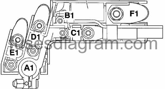
Terminal No. | Description |
A1 | Battery Postive Terminal |
B1 | Terminal to Energy Management Control Module |
C1 | Safety Fuse 1 (40A), not used |
D1 | Safety Fuse 2(110A), Power Supply Fuse Holder in Luggage Compartment, right |
E1 | Safety Fuse 3(110A), Power Supply Vehicle Electrical System, ABS Control Module |
F1 | Terminal to Starter -B- |