For the Volkswagen Golf MK5 2003, 2004, 2005, 2006, 2007, 2008 model year.
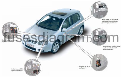
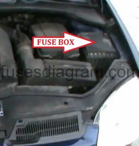
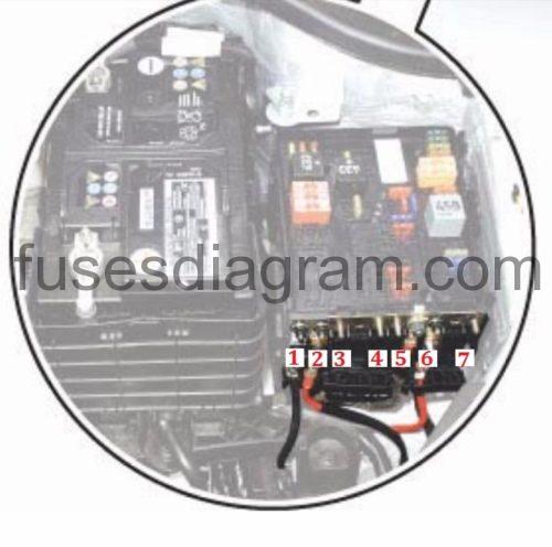
Fuse box located.
Fuse box on left in engine compartment Golf 5.
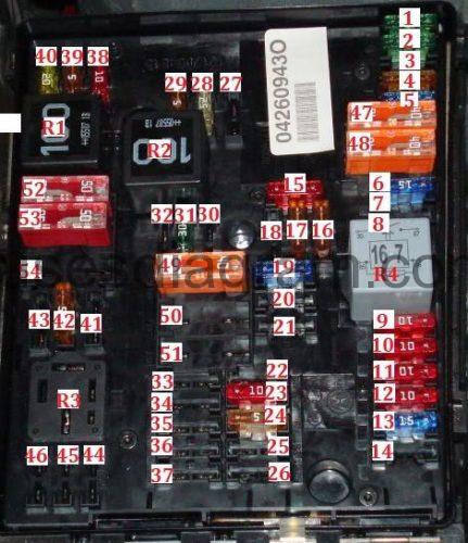
fuse box diagram type 1.
legend.
R1 | Ignition main circuits relay 2 |
R2 | Starter motor relay |
R3 | Fuel pump relay-1,4 (BCA)/1,6(BGU) |
R4 | Ignition main circuits relay 1 |
F1 | (30A) Anti-lock brake system (ABS) |
F2 | (30A) Anti-lock brake system (ABS) |
F3 | (20A) Multifunction control module2 |
F4 | (5A) Multifunction control module 1 |
F5 | (20A) Horn |
F6 | (5A/20A) Engine management |
F7 | (5A) Brake pedal position(BPP) switch, clutch position potentiometer |
F8 | (10A) Engine coolant blower motor control module, engine management |
F9 | (10A) Engine management |
F10 | (10A) Engine management |
F11 | (25A) Engine management-petrol |
F12 | (15A) Engine management |
F13 | (20A) Automatic transmission(AT) |
F14 | – |
F15 | (40A) Starter motor |
F16 | (15A) Steering column function control module |
F17 | (10A) Instrument panel |
F18 | – |
F19 | (15A) Audio system, navigation system |
F20 | (10A)Telephone |
F21 | – |
F22 | – |
F23 | (10A) Cruise control |
F24 | (10A) Data bus connection |
F25 | – |
F26 | (5A) Engine management-Diesel |
F27 | (10A) Crank case breather heater |
F28 | (20A) Automatic transmission(AT) |
F29 | (20A) Engine management |
F30 | (20A) Heater/air-conditioning (AC) |
F31 | (25A) Windscreen wipers |
F32 | (10A) Engine management |
F33 | (15A) Fuel lift pump |
F34 | – |
F35 | – |
F36 | – |
F37 | – |
F38 | (10A) Head lamp adjustment |
F39 | (5A) Engine oil tem perature sensor, instrument panel |
F40 | (20A) Fascia fuse box/relay plate 1(F1-F11/F29-F31) |
F41 | – |
F42 | (5A) Engine management-petrol |
F43 | – |
F44 | – |
F45 | – |
F46 | – |
F47 | (40A) Multifunction control module 1 |
F48 | (40A) Multifunction control module 1 |
F49 | (50A) Multifunction control module 1 |
F50 | (40A) Audio system |
F51 | (50A) Glow plug control module |
F52 | (50A) Multifunction control module1 |
F53 | (50A) Fascia fuse box/relay plate 1 (F32-F37), fascia fuse box/relay plate 2 (F4) |
F54 | – |
codes as follow type 2.
R1 | Engine control (EC) relay |
R2 | Engine coolant pump relay |
R3 |
|
R4 | Engine control (EC) relay |
F1 | (30A) ABS control module |
F2 | (30A) ABS control module |
F3 |
|
F4 | (5A) |
F5 | (15A) |
F6 | (15A) Engine management system |
F7 |
|
F8 |
|
F9 | (10A) Engine management system |
F10 | (10A) Engine management system |
F11 | (10A) Engine management system |
F12 | (10A) Engine management system |
F13 | (15A) Transmission control module (TCM) |
F14 |
|
F15 | (10A) Engine coolant pump motor |
F16 | (5A) Steering column function control module |
F17 | (5A) Instrument panel |
F18 | (30A) Audio system |
F19 | (15A) |
F20 | (5A) Telephone control module |
F21 |
|
F22 |
|
F23 | (10A) Engine control module(ECM) |
F24 | (5A) CAN data bus gateway control module |
F25 |
|
F26 |
|
F27 |
|
F28 | (15A) Engine control module(ECM) |
F29 | (10A) Engine coolant pump motor |
F30 | (20A) Auxiliary heater control module |
F31 | (30A) Wind screen wash/wipe system |
F32 | – |
F33 | – |
F34 | – |
F35 | – |
F36 | – |
F37 | – |
F38 | (10A) |
F39 | (5A) Clutch pedal position (CPP) switch |
F40 | (20A) Engine management system |
F41 | – |
F42 | (5A) Engine management system |
F43 | – |
F44 | – |
F45 | – |
F46 | – |
F47 | (40A) |
F48 | (40A) |
F49 | (40A) Ignition main circuits |
F50 | – |
F51 | – |
F52 | (40A) Starting system |
F53 | (50A) |
F54 | – |
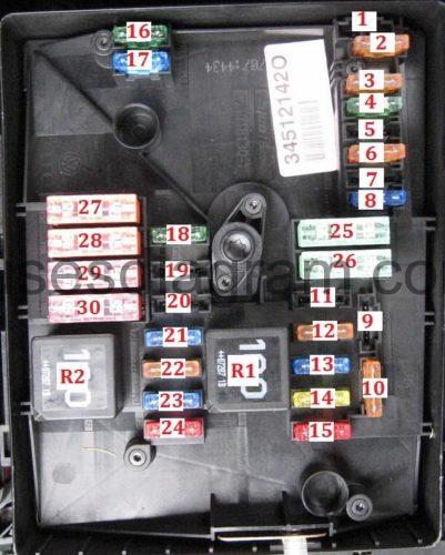
fuse box diagram type 2.
legend.
R1 | Engine control (EC)relay |
R2 | Secondary air injection (AIR) pump relay |
F1 | – |
F2 | (5A) Steering column function control module |
F3 | (5A) |
F4 | (30A) ABS control module |
F5 | (15A) Transmission control module (TCM) |
F6 | (5A) Instrument panel |
F7 | – |
F8 | (15A) |
F9 | (5A) Telephone control module |
F10 | (5A/10A) Engine control module (ECM) |
F11 | (20A) Auxiliary heater control module |
F12 | (5A) CAN data bus gateway control module |
F13 | (15A/30A) Engine control module(ECM) |
F14 | (20A) Engine management system |
F15 | (5A/10A) Engine management system |
F16 | (30A) ABS control module |
F17 | (15A) |
F18 | (30A) Audio system |
F19 | (30A) Wind screen wash/wipe system |
F20 | – |
F21 | (10A/15A) Engine management system |
F22 | (5A) Clutch pedal position (CPP) switch |
F23 | (5A/10A/15A) Engine management system |
F24 | (10A) Engine management system |
F25 | (40A) |
F26 | (40A) |
F27 | (50A) Glow plug control module |
F28 | (40A) Ignition main circuits |
F29 | (50A) |
F30 | (40A) Starting system |
Pre-fuse box, on left in engine compartment Volkswagen Golf 5.
legend type 1.
F1 | (150A/200A) Altimeter |
F2 | (80A) Power steering |
F3 | (80A) Engine coolant blower motor control module |
F4 | – |
F5 | (100A) Auxiliary heater |
F6 | (50A) Fascia fuse box/relay plate 1 (F12-F17/F20/F22-F27/F43-F45) |
F7 | – |
legend type 2.
F1 | (200A) Altimeter |
F2 | (80A) Power steering |
F3 | (50A) Engine coolant blower motor |
F4 | – |
F5 | (80A) |
F6 | – |
F7 | – |
legend type 3.
F1 | (150A/200A) Alternator |
F2 | (80A) Power steering |
F3 | (50A) Engine coolant blower motor |
F4 | – |
F5 | (80A) |
F6 | (100A) Auxiliary heater |
F7 | – |
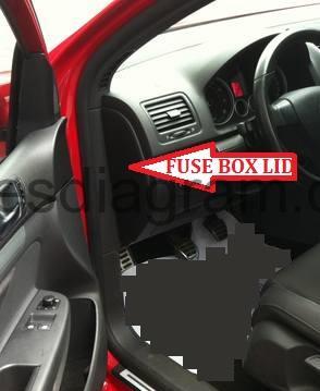
Fuse box in passenger compartment Volkswagen Golf 5.
Fuse box location.
Fuse box on left in dash panel.
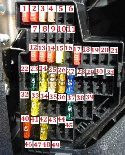
fuse box diagram.
legend type1.
F1 | (10A) Data link connector (DLC) |
F2 | (5A) Anti-lock brake system (ABS) |
F3 | (10A) Power steering |
F4 | (5A) Heated seats, heater/air-conditioning (AC) |
F5 | (5A) Brake pedal position(BPP)switch, clutch position potentiometer |
F6 | (5A) Data bus connection, engine management, instrumentation control module |
F7 | (5A) Headlamp level control module |
F8 | (5A) Interior rearview mirror |
F9 | (5A) Four-wheel drive control module |
F10 | (5A)Telephone |
F11 | (5A) Trailer control module |
F12 | (10A) Door function control module, driver, door function control module, passenger |
F13 | (10A) Data link connector (DLC), light switch |
F14 | (5A) Brake pedal position (BPP)switch |
F15 | (7,5A) Multifunction control module1 |
F16 | (10A) Heater/air-conditioning(AC) |
F17 | (5A) Audio system, wind screen wiper rain sensor |
F18 | (5A) Parking aid control module |
F19 | – |
F20 | (5A) Anti-lock brake system (ABS)-TevesMk60 |
F21 | – |
F22 | (40A) Heater/air-conditioning (AC) |
F23 | (30A) Electric windows |
F24 | (25A) Cigarette lighter |
F25 | (25A) Multifunctioncontrolmodule1 |
F26 | (20A) Charging socket |
F27 | (15A) Engine management |
F28 | – |
F29 | (10A) Engine management |
F30 | (5A) Airbag |
F31 | (5A) Reversing lamps |
F32 | (15A) Electric windows |
F33 | (25A)Sunroof |
F34 | (15A) Electric seats |
F35 | (5A) Alarm system |
F36 | (20A) Head lamp washers |
F37 | (30A) Heated seats |
F38 | – |
F39 | – |
F40 | (40A) Heater/air-conditioning (AC) |
F41 | (15A) Rear screen wash/wipe system |
F42 | (15A) Wind screen washers |
F43 | (15A) Trailer control module |
F44 | (20A) Trailer control module |
F45 | (15A) Trailer control module |
F46 | (5A) Heater/air-conditioning (AC), wind screen washer jet heaters |
F47 | (5A) Heater/air conditioning (AC) |
F48 | (7,5A) Electric seats, steering column adjustment |
F49 | (7,5) light switch |
legend type 2.
F1 | (10A) |
F2 | (10A) |
F3 | (5A) Supplementary restraint system (SRS) control module |
F4 | (5A) |
F5 | – |
F6 | – |
F7 | – |
F8 | – |
F9 | – |
F10 | – |
F11 | – |
F12 | (10A) Door function control modules |
F13 | (10A) |
F14 | (10A) |
F15 | (7,5A) |
F16 | – |
F17 | (5A) |
F18 | – |
F19 | – |
F20 | – |
F21 | – |
F22 | (40A) Heater blower motor |
F23 | (30A) Door function control modules |
F24 | (20A) |
F25 | (25A) Cigarette lighter |
F26 | (30A) Door function control modules |
F27 | (15A) Fuel pump(FP) control module |
F28 | – |
F29 | – |
F30 | (10A) |
F31 | – |
F32 | (30A) Auxiliary power socket |
F33 | (25A) Sun roof control module |
F34 | (15A) Electric seats |
F35 | – |
F36 | (20A) Head lamp washers |
F37 | (30A) Heated seats |
F38 | – |
F39 | (20A) Sun roof control module |
F40 | (40A) |
F41 | (15A) |
F42 | (15A) |
F43 | (15A) Trailer control module |
F44 | (20A) Trailer control module |
F45 | (15A) Trailer control module |
F46 | – |
F47 | – |
F48 | – |
F49 | – |
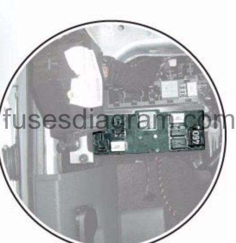
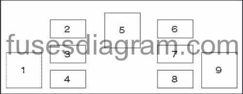
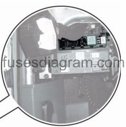
Relay carrier of onboard power supply control unit on left under dash panel.
description type 1.
1 | – |
2 | Door mirror heater relay |
3 | – |
4 | Multifunction control module relay |
5 | Heated rear window relay |
6 | Horn relay |
7 | Windscreen washer pump relay 1 |
8 | Windscreen washer pump relay 2 |
9 | Ignition auxiliary circuits relay |
description type 2.
1 |
|
2 | – |
3 | – |
4 |
|
5 | Heated rear window relay |
6 | Horn relay |
7 |
|
8 |
|
9 | Cranking cut-off relay, auxiliary circuits |
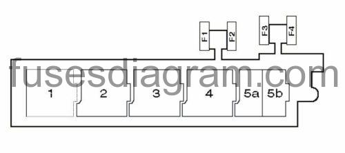
Relay carrier, on left beneath dash panel, above onboard power supply control unit.
identifying type 1.
1 | Headlamp washer pump relay |
2 | Fuel lift pump relay – Diesel |
3 | – |
4 | Headlamp washer pump relay |
5a | Fuel system primer relay |
5b | Auxiliary heater relay |
F1 | – |
F2 | – |
F3 | – |
F4 | Electric seats circuit breaker |
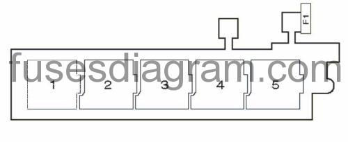
identifying type 2.
| 1 | |
| 2 | |
| 3 | Starter motor relay |
| 4 | Headlamp washer pump relay |
| 5 | Fuel pump (FP) relay |
| F1 | (20A) Electric seats circuit breaker |


