
For Volkswagen Touareg 2002, 2003, 2004, 2005, 2006, 2007, 2008, 2009, 2010 model year.
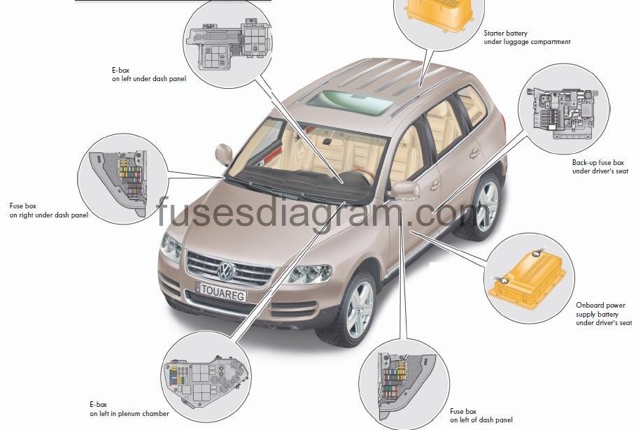
Fuse box location.
engine code
Engines are identified by a 3 or 4 letter code stamped on the engine. Engine codes are also located on the vehicle data plate.
Year | Displacement | Engine Code |
2004-06 | 3.2L (V6) | BAA |
2004-07 | 4.2L (V8) | AXQ |
2004 | 5.0L (V10) | BKW |
2005-06 | 3.2L (V6) | BMX |
2006-09 | 3.6L (V6) | BHK |
2007-09 | 4.2L (V8) | BAR |
2007-08 | 5.0L (V10) | BWF |
2009 | 3.0L (V6) | CATA |
fuse color identification.
Fuse Color | Amp Rating |
Black | 1A |
Violet | 2A |
Lilac | 3A |
Beige | 5A |
Brown | 7.5A |
Red | 10A |
Blue | 15A |
Yellow | 20A |
White | 25A |
Green | 30A |
Orange | 40A |
Red | 50A |
Blue | 60A |
Transparent | 80A |
Engine compartment – relays and fuses.
electronic box in left plenum chamber – fuses/relays (v10 tdi diesel engine)
fuse box diagram.
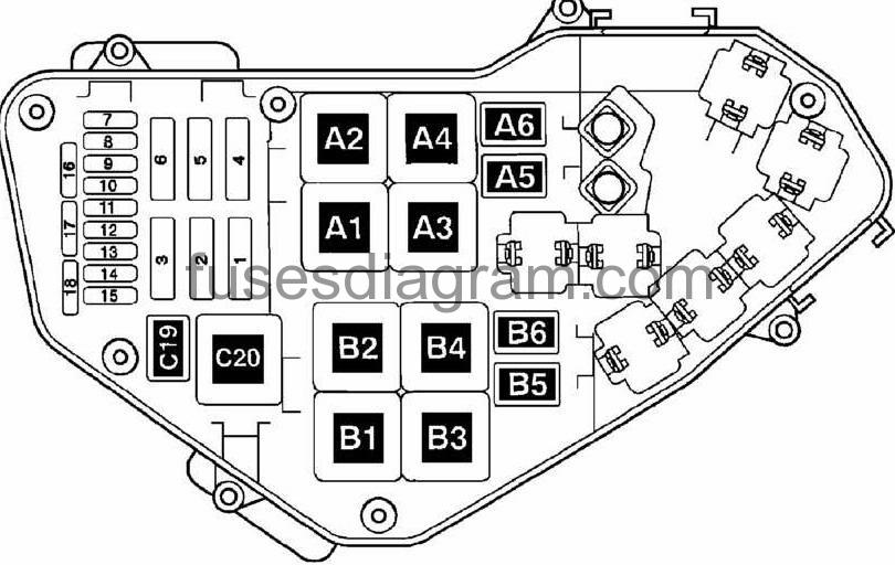
identifying fuses (e-box in plenum chamber – left side – v10 tdi)
Fuse No. | Wiring ID | Rating Amperage | Function/Component |
1 | S1 | 60A | -Coolant Fan 1 |
2 | S2 | 30A | -Coolant Fan 2 |
3 | S3 | 60A | -Glow plugs 1 |
4 | S4 | 60A | -Glow plugs 2 |
5 | S5 | – | Open |
6 | S6 | 60A | -Fuel Pump (FP), ignition system (only vehicles with second battery) |
7 | SD7 | 10A | -Fuel cooling, auxiliary coolant pump |
8 | S8 | 30A | -Engine Control Module (ECM) 2 |
9 | S9 | 30A | -Engine Control Module (ECM) 1 |
10 | S10 | 10A | -A/C pressure sensor, EGR valve, Fuel Pump (FP)/ignition coil, coolant fan control modules |
11 | S11 | 15A | -Thermostat for regulated engine cooling, A/C compressor regulation, engine oil temperature/level sender, turbocharger valves 1 and 2, intake manifold tuning valves 1 and 2 |
12 | S12 | 5A | -Glow plug relays 1 and 2, Auxiliary Fuel Pump (FP), fuel cooling, brake switch |
13 | S13 | 15A | -Fuel pump (FP)1 |
14 | S14 | – | Open |
15 | S15 | 10A | -Power Supply Relay Terminal 30 |
16 | S16 | 10A | -Parallel Battery Switch Relay |
17 | S17 | 20A | -Oxygen Sensor (O2S) – Diesel 1 and 2 |
18 | S18 | – | Open |
identifying relays (e-box in plenum chamber – left side – v10 tdi)
Location No. | Component/Circuit Protected |
A1 | J703- Glow/Time Control Module 2 (410) |
A2 | J689- A2 Power Supply Relay (Terminal 30, B+) Relay 2 (219) |
A3 | J179- A3 Automatic Glow Time Control Module (410) |
A4 | Not Used |
A5 | J496- Auxiliary Engine Coolant (EC) Pump Relay (404) |
A6 | J445- Relay for pump, fuel cooling (404) |
B1 | J317- Power Supply (Terminal 30, B+) Relay (219) |
B2 | J17- Fuel Pump (FP) Relay (53) |
B3 | Not Used |
B4 | J701- Power Supply Relay 1 (100) |
B5 | Not Used |
B6 | Not Used |
C19 | Not Used |
C20 | J682- Power Supply Relay (terminal 50) (433) |
identifying fuses (e-box in plenum chamber – left side – engine code baa)
Fuse No. | Wiring ID | Rating Amperage | Function/Component |
1 | S1 | 60A | -Coolant Fan 1 |
2 | S2 | 30A | -Coolant Fan 2 |
3 | S3 | 40A | -Secondary Air Injection (AIR) Pomp Motor |
4 | S4 | – | Open |
5 | S5 | – | Open |
6 | S6 | – | Open |
7 | SD7 | 20A | -Ignition Coils with Power Output Stage Cyl. 1-3 Injectors – Cyl. 1-3 |
8 | S8 | 20A | -Ignition Coils with Power Output Stage Cyl. 4-6 Injectors – Cyl. 4-6 |
9 | S9 | 30A | -Motoronic Engine Control Module (ECM) Valve 1 for camshaft adjustment, Camshaft Adjustment Valve 1 (exhaust), Intake Manifold Change-Over Valve |
10 | S10 | 10A | -Leak Detection Pump (LDP), High Pressure Sensor (A/C), Evaporative Emission (EVAP) Canister Purge Solenoid Valve, Evaporative Emission (EVAP) Canister Purge Regulator Valve, Coolant FC (Fan Control) Control Module, Coolant FC (Fan Control) Control Module 2, Brake Booster Relay |
11 | S11 | 15A | -A/C Compressor, Climatronic Control Module |
12 | S12 | 5A | -Secondary Air Injection (AIR) Pump Relay, Coolant Circulation Pump Relay |
13 | S13 | 15A | -Fuel pump (FP) |
14 | S14 | 15A | -Transfer Fuel pump (FP) |
15 | S15 | 10A | -Motronic Engine Control Module (ECM) Power Supply Relay, Motronic Engine Control Module (ECM) Power Supply Relay 2, Fuel Pump (FP) Relay, Fuel Pump (FP) 2 Relay |
16 | S16 | 30A | -Coolant Circulation Pump Relay, Brake Booster Relay |
17 | S17 | 15A | -Heated Oxygen Sensor (HO2S) (G39 & C108 – heating elements) |
18 | S18 | 7.5A | -Heated Oxygen Sensor (HO2S) (G130 & G131 – heating elements) |
Identifying relays (e-box in plenum chamber – left side – engine code baa)
Location No. | Component/Circuit Protected |
A1 | J670- Motronic Engine Control Module (ECM) Power Supply Relay 2 (53) |
A2 | Not Used |
A3 | J271- Motronic Engine Control Module (ECM) Power Supply Relay (167) |
A4 | J299- Secondary Air Injection (AIR) Pump Relay (100) |
A5 | J496- Auxiliary Engine Coolant (EC) Pump Relay (404) |
A6 | J17- Fuel Pump (FP) Relay (404) |
B1 | Not Used |
B2 | Not Used |
B3 | Not Used |
B4 | Not Used |
B5 | Not Used |
B6 | J569- Brake Booster Relay (404) |
C19 | J49- Fuel Pump (FP) 2 Relay (404) |
C20 | J682- Power Supply Relay (terminal 50) (433) |
identifying fuses (e-box in plenum chamber – left side – engine code bhx axq )
Fuse No. | Wiring ID | Rating Amperage | Function/Component |
1 | S1 | 60A | -Coolant Fan 1 |
2 | S2 | 30A | -Coolant Fan 2 |
3 | S3 | 40A | -Secondary Air Injection (AIR) Pomp Motor |
4 | S4 | 40A | -Secondary Air Injection (AIR) Pomp Motor 2 |
5 | S5 | – | Open |
6 | S6 | – | Open |
7 | SD7 | 20A | -Ignition Coils with Power Output Stage Cyl. 1-8 |
8 | S8 | 20A | -Injectors – Cyl. 1-8 |
9 | S9 | 30A | -Motoronic Engine Control Module (ECM) Intake Manifold Tuning (IMT) Valve 1, Valve 1 for camshaft adjustment, Valve 2 for camshaft adjustment, Intake Manifold Change-Over Valve |
10 | S10 | 10A | -Leak Detection Pump (LDP), High Pressure Sensor (A/C), Evaporative Emission (EVAP) Canister Purge Solenoid Valve, Evaporative Emission (EVAP) Canister Purge Regulator Valve, Coolant FC (Fan Control) Control Module, Coolant FC (Fan Control) Control Module 2, Brake Booster Relay, Oil Level Thermal Sensor, A/C Compressor Regulator, Climatronic Control Module |
11 | S11 | 15A | -Secondary Air Injection (AIR) Solenoid Valve |
12 | S12 | 5A | -Secondary Air Injection (AIR) Pump Relay |
13 | S13 | 15A | -Fuel Pump (FP) |
14 | S14 | 15A | -Transfer Fuel Pump (FP) |
15 | S15 | 10A | -Motronic Engine Control Module (ECM), Motronic Engine Control Module (ECM) Power Supply Relay, Fuel Pump (FP) Relay, Fuel Pump (FP) 2 Relay |
16 | S16 | 30A | -Brake Booster Relay, Brake System Vacuum Pump, Coolant Pump, Recirculation Pump (with auxiliary heater only) |
17 | S17 | 15A | -Heated Oxygen Sensor (HO2S) (G39 & C108 – heating elements) |
18 | S18 | 7.5A | -Heated Oxygen Sensor (HO2S) (G130 & G131 – heating elements) |
identifying relays (e-box in plenum chamber – left side – engine code bhx axq )
Location No. | Component/Circuit Protected |
A1 | Not Used |
A2 | Not Used |
A3 | J271- Motronic Engine Control Module (ECM) Power Supply Relay (614) |
A4 | J299- Secondary Air Injection (AIR) Pump Relay (100) |
A5 | J496- Auxiliary Engine Coolant (EC) Pump Relay (404) |
A6 | J49- Fuel Pump (FP) 2 Relay (404) |
B1 | Not Used |
B2 | Not Used |
B3 | J545- Secondary Air Injection (AIR) Pump Relay 2 (100) |
B4 | Not Used |
B5 | Not Used |
B6 | J569- Brake Booster Relay (404) |
C19 | J17- Fuel Pump (FP) Relay (404) |
C20 | J682- Power Supply Relay (terminal 50) (433) |
Luggage compartment – relay.
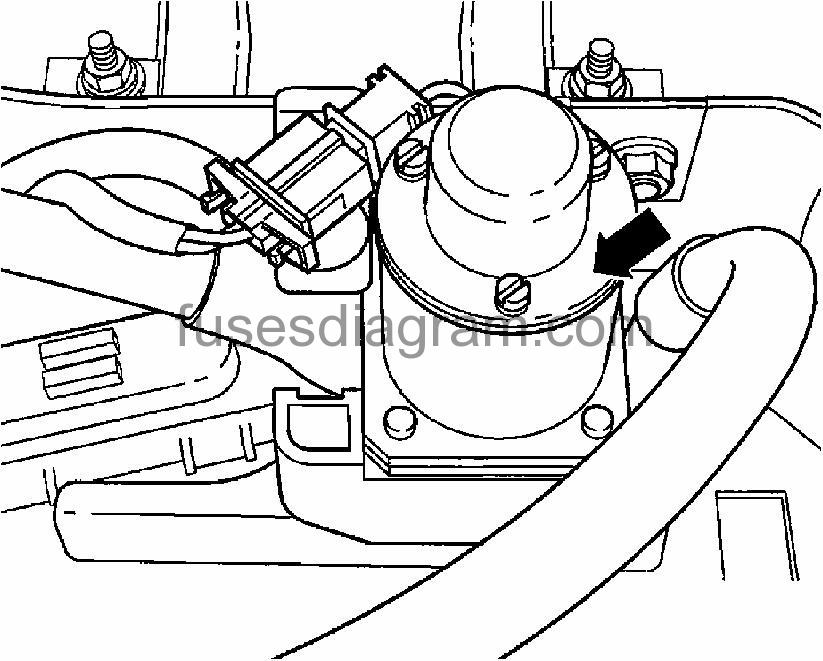
parallel battery connection relay
The parallel battery connection relay (J581) is located near the second battery in the luggage compartment (where applicable).
Passenger compartment Volkswagen Touareg – relays and fuses.
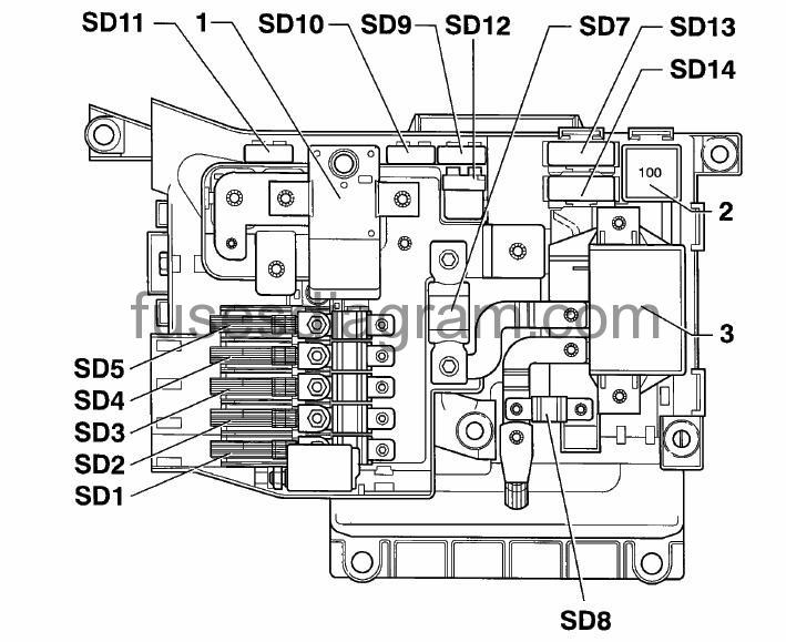
main fuse/relay box "sd" under driver seat.
The relay/fuse panel "SD" is located below the driver's seat, refer to illustration below.
fuse box layout.
identifying fuses (main fuse panel (sd) below driver seat – left side).
Location | Wiring ID | Rating (A) | Function/Component |
1 | SD1 | 150A | -Fuse for left side instrument panel fuse box |
2 | SD2 | 150A | -Fuse for right side instrument panel fuse box |
3 | SD3 | 60A | -Fuse for right side instrument panel fuse box |
4 | SD4 | 60A | -Fuse for Electronic Box |
5 | SD5 | 60A | -Power Supply Relay (terminal 15) |
6 | – | – | Not Used |
7 | SD7 | 250A | -Second Battery Charge Relay |
8 | SD8 | 150A | -Fuse for Electronic Box |
9 | SD9 | 5A | -Vehicle Electrical Equipment Control Module |
10 | SD10 | 10A | -Vehicle Electrical Equipment Control Module |
11 | SD11 | 5A | -Starter Circuit Diagnostic |
12 | – | – | Not Used |
13 | SD13 | 40A | – Level Control System Compressor Relay |
14 | – | – | Not Used |
identifying relays (main fuse panel (sd) below driver seat – left side).
Component No. | Circuit Protected |
1 | E74- Main Battery Switch (with reset) |
2 | J329- Voltage Supply Terminal 15 (B+) Relay (433, 100) where applicable |
3 | J713- Second Battery Charge Relay |
identifying fuses (main fuse panel (sd) below driver seat – left side – from may 2006).
Location | Wiring ID | Rating (A) | Function/Component | Terminal |
1 | SD1 | 150A | – Fuse panel B (SB1 – SB6, SB7 – SB12, SB14 – SB19, SB22 – SB25, SB33 – SB36, SB38, SB41, SB42 – SB45, SB56, SB57) | 30 |
2 | SD2 | 150A | – Fuse panel C (SC1-SC4, SC5-SC8, SC14- SC19, SC20-SC25, SC27-SC30, SC53, SC54, SC56, SC57) | 30 |
3 | SD3 | 60A | – Fuse panel C (SC9 – SC12) | 30 |
4 | SD4 | 60A (1) | – Fuse panel B (SB38 – SB41) (1) | 30 |
5 | SD5 | 60A | -J329 – Power Supply Relay (terminal 15) | 30 |
6 | – | – | Not Used | 30 |
7 | SD7 | 250A WO | -J713- Second Battery Charge Relay (1)(2) | 30 |
8 | SD8 | 150A (1) 60A (2) | -Fuse panel B (SB1 – SB6, SB56) – Power Supply Relay 1 | 30 |
9 | SD9 | 5A | -J519- Vehicle Electrical System Control Module | 30 |
10 | SD10 | 10A (1) | -J519- Vehicle Electrical System Control Module (1) | 30 |
11 | SD11 | 5A | -J519- Vehicle Electrical System Control Module | 30 |
12 | – | – | Not Used | 30 |
13 | SD13 | 40A | -J403- Level Control System Compressor Relay | 30 |
14 | SD14 | 40A | -J742- Stabilizer Decoupling Control Module | 30 |
| ||||
relays.
Component No. | Circuit Protected |
1 | Main Battery Switch with Reset -E74 |
2 | Voltage Supply Terminal 15 (B+) Relay -J329 (433) |
3 | Second Battery Charge Relay -J713 |
Fuse box "sb" instrument panel – left side.
The fuse box (holder) panel is located behind trim panel on far left side of dashboard, see illustration below. Fuses in left side instrument panel fuse box are identified with prefix "SB" in wiring diagrams.
fuse box diagram.
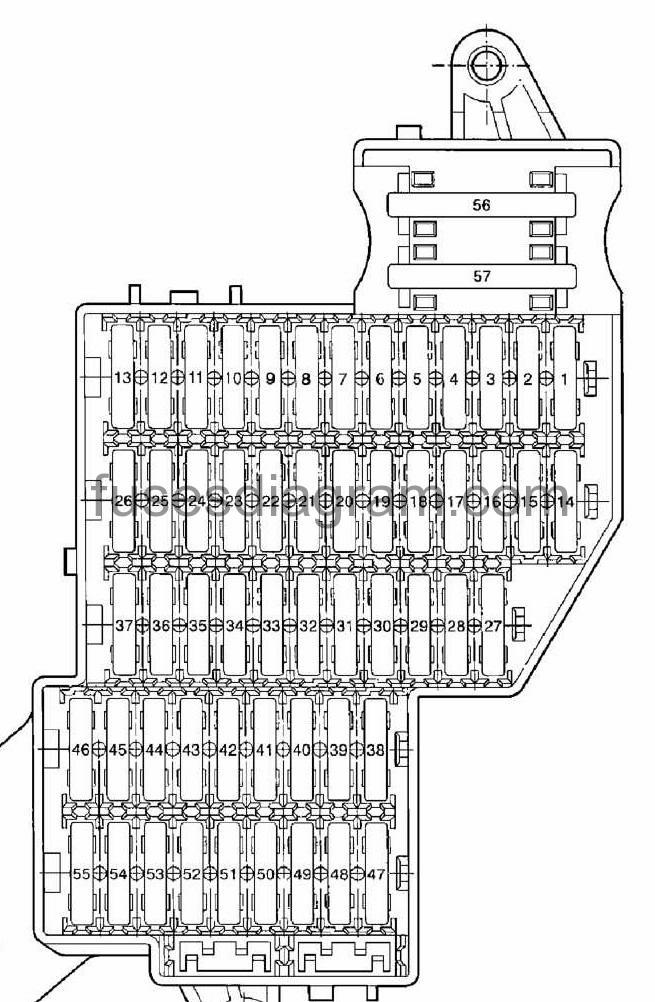
Identifying Fuse Box "SB" Instrument Panel – Left Side.
Fuse No. | Wiring ID | Rating Amperage | Function/Component |
1 | SB1 | 20A | Cigarette lighter – front |
2 | SB2 | 5A | Auxiliary heater – timer (where applicable) |
3 | SB3 | 20A | 12V Outlet (footwell), 12V Outlet (center console front) |
4 | SB4 | 15A | Auxiliary heater (where applicable) |
5 | SB5 | 20A | 12V Outlet – Center console rear, Cigarette lighter rear |
6 | SB6 | 15A | Access/start control module |
7 | SB7 | 5A | Data Link Connector (DLC), Antenna switch |
8 | SB8 | 30A | Wiper motor |
9 | – | 15A | Vehicle electrical system control module – Windshield washer pump |
10 | SB10 | 25A | Left rear window lifter |
11 | SB11 | 15A | Door control modules – Central Locking System (left rear & left front) |
12 | SB12 | 15A | Vehicle electrical system control module – Interior lights |
13 | – | – | Not Used |
14 | SB14 | 25A | Left front window lifter |
15 | SB15 | 15A | Central control module for comfort system – Left tail lamps |
16 | SB16 | 20A | Vehicle electrical system control module – Horns |
17 | SB17 | 10A | Vehicle electrical system control module – Left parking lamps, Turn signals |
18 | SB18 | 10A | Headlamp washer pump |
19 | SB19 | 10A | Vehicle electrical system control module – Fog lamps |
20 | – | – | Not Used |
21 | SB21 | 15A | Vehicle electrical system control module |
22 | SB22 | 30A | Differential lock control module |
23 | SB23 | 10A | Differential lock control module |
24 | SB24 | 5A | Tire pressure monitoring control module |
25 | SB25 | 15A | Power steering column adjustment |
26 | SB26 | 10A | Airbag control module, Motronic Engine Control Module (ECM), Instrument cluster, Brake/Clutch switches, ESP, Mass Air Flow (MAF) Sensor |
27 | – | – | Not Used |
28 | SB28 | 5A | Brake light disable relay, Brake switch (where applicable) |
29-32 | – | – | Not Used |
33 | SB33 | 5A | Steering column electronic systems control module |
34 | SB34 | 5A | Alarm system (sensor), Heated seat relay (through 10/2003) |
35 | SB35 | 15A | Vehicle electrical system control module – Headlamps (high/low beam) |
36 | SB36 | 10A | Vehicle Electrical System Control Module |
37 | – | – | Not Used |
38 | SB38 | 10A | Brake light switch |
39 | SB39 | 5A | Manual A/C, Power supply relay, Instrument cluster, Rear window defogger relay, Heated seat relay (through 10/2003) |
40 | SB40 | 5A | Instrument cluster |
41 | SB41 | 15A | Access/start control module |
42 | SB42 | 30A | Power sunroof |
43 | – | – | Not Used |
44 | SB44 | 30A | Power steering column adjustment, Power seats, Power seats (with memory) control module |
45 | SB45 | 30A | Left front power seat, Rear seat heating control modules |
46 | – | – | Not Used |
47 | SB47 | 10A | Differential lock control module |
48 | SB48 | 5A | Auxiliary heater (where applicable) |
49 | SB49 | 5A | Servotronic control module |
50 | SB50 | 10A | Positive Crankcase Ventilation (PCV) Heating Element, Secondary Air (AIR) Solenoid |
51 | SB51 | 5A | Air quality sensor, Seat heaters, Electronic parking |
52 | SB52 | 30A | Rear wiper motor |
53 | SB53 | 5A | Mirror heating, Light switch, Steering column electronics control module |
54 | SB54 | 10A | Headlamp range control |
55 | SB55 | 15A | Auxiliary heater relay (where applicable) |
56 | SB56 | 40A | Blower – Climatronic 2-Zone |
57 | SB57 | 40A | Rear blower – Climatronic 4-Zone |
Fuse box "sc" instrument panel – right side.
The fuse box (holder) panel is located behind trim panel on far right side of dashboard, see illustration below. Fuses in right side instrument panel fuse box are identified with prefix "SC" in wiring diagrams.
fuse box layout.
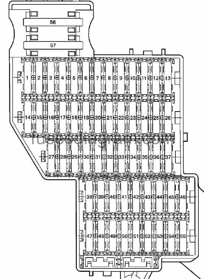
Identifying Fuse Box "SC" Instrument Panel – Right Side.
No. | ID | Amps |
|
1 | SC1 | 15A | Trailer wiring, control module for towing sensor (where applicable) |
2 | SC2 | 5A | Control module for parking aid |
3 | SC3 | 15A | Control module for towing sensor (where applicable) |
4 | SC4 | 5A | Telematics, telephone (where applicable) |
5 | SC5 | 15A | Control module for towing sensor (where applicable) |
6 | SC6 | 30A | ABS control module (w/EDL) |
7 | SC7 | 5A | Differential control module |
8 | SC8 | 20A | Vehicle electrical system control module – Lamps |
9 | SC9 | 5A | CD-Changer |
10 | SC10 | 5A | TV Tuner (where applicable) |
11 | SC11 | 10A | Radio |
12 | SC12 | 20A | Amplifier, Antenna switch |
13 | – | – | Not Used |
14 | SC14 | 15A | Central control module for comfort system – Right tail lamps |
15 | SC15 | 25A | Right rear window lifter |
16 | SC16 | 10A | Luggage compartment lamps |
17 | SC17 | 15A | Vehicle electrical system control module – Headlamps (high/low beam) |
18 | SC18 | 30A | Rear Window Defogger Relay |
19-20 | – | – | Not Used |
21 | SC21 | 10A | Alarm horn, Spare tire lock |
22 | SC22 | 30A | Right front power seat, front heated seat control modules |
23 | SC23 | 10A | Climatronic control module |
24 | SC24 | 30A | Passenger memory seat control module |
25 | SC25 | 5A | Rear A/C control head (Climatronic) |
26 | – | – | Not Used |
27 | SC27 | 15A | Level control system control module |
28 | – | – | Not Used |
29 | SC29 | 15A | Transmission Control Module (TCM) |
30 | SC30 | 20A | Closing assist relay |
31 | SC31 | 15A | Central control module for comfort system |
32 | SC32 | 10A | Door control modules – Central Locking System (right front & right rear) |
33 | – | – | Not Used |
34 | SC34 | 25A | Right front window lifter |
35 | SC35 | 10A | Vehicle electrical system control module Right parking lamps, turn signals |
36 | SC36 | 5A | Roof module, telephone, compass (where applicable) |
37 | – | – | Not Used |
38 | SC38 | 10A | ABS control module (w/EDL) |
39 | – | – | Not Used |
40 | SC40 | 10A | Differential control module |
41 | SC41 | 10A | Control module for towing sensor (where applicable) |
42 | SC42 | 5A | Garage door opener control module, Garage door opener indicator lamp |
43 | SC43 | 5A | Back-Up light switch |
44 | SC44 | 5A | Heated washer nozzles, Level control system control head, Heated seat adjuster front & rear through 10/2003 |
45-47 | – | – | Not Used |
48 | SC48 | 10A | Level control system control module |
49 | SC49 | 5A | Power mirrors telematics telephone (where applicable) |
50 | SC50 | 5A | Control module for parking aid |
51 | SC51 | 20A | Transmission Control Module (TCM) |
52 | SC52 | 5A | Tiptronic switch Multi-Function Transmission Range (IR) Switch selector lever park position |
53-55 | – | – | Not Used |
56 | SC56 | 40A | ABS control module (w/EDL) |
57 | SC57 | 40A | Differential control module |
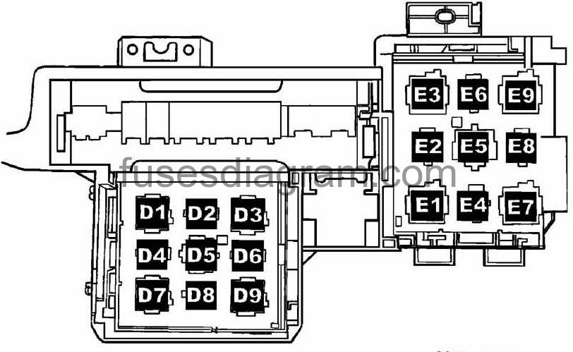
Electronic box behind instrument panel left side – relays.
Component No. | Component/Circuit Protected |
D1 | J236- Servotronic Control Module (463) |
D2 | J714- Closing Assist Relay (404) |
D3 | J403- Relay for compressor level control system (214) |
D4 | Open |
D5 | J329- Voltage Supply Terminal 15 (B+) Relay (433) |
D6 | J493- Additional Water Heater Relay (404) |
D7 | J9- Rear Window Defogger Relay (53) |
D8 | J83- Heated Seat Relay (404) to 01/2003 |
D9 | J419- Auxiliary relay for brake light (444) |
E1 | J309- Solar Cell Separation Relay (79) |
E2 | J732- Spare Tire Unlock Relay (404) |
E3 | J32- A/C Relay (53) |
E4 | J160- Recirculation Pump Relay (404) |
E5 | Open |
E6 | Open |
E7 | J39- Relay for headlamp cleaning system (53) |
E8 | J708- Residual Heat Relay (404)(engine codes BAA & BHX only) |
E9 | Open |
*: Not all relays listed in table are applicable to USA/CDN market. | |