For the Alfa Romeo Brera 2005, 2006, 2007, 2008, 2009, 2010, 2011 model year.
| Cigarette lighter fuse – (fuse box in passenger compartment, fuse №44/10A) |
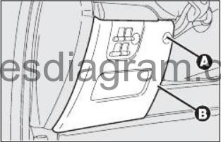
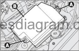
Fuse box in passenger compartment.
fuse box location.
To gain access to the fuses in the fuse box on the dashboard, loosen the fas-tening screw A and remove the cover B.
fuse box diagram.
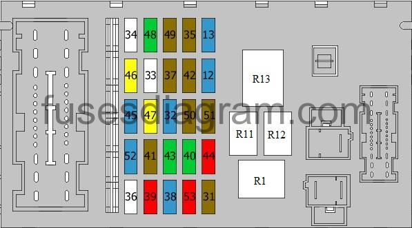
legend.
| Fuse | Amps | Circuits protected |
|---|---|---|
| 12 | 15A | Right dipped beam |
| 13 | 15A | Left dipped beam |
| 31 | 7,5A | Relay (coil) |
| 32 | 15A | Door control unit Keyless entry receiver |
| 33 | Spare fuse | |
| 34 | Spare fuse | |
| 35 | 7,5A | Reversing light(s) Cruise control unit AQS sensor Water sensor, fuel filter |
| 36 | Spare fuse | |
| 37 | 7,5A | Brake light(s) Dashboard power, standard functions Xenon light(s) |
| 38 | 15A | Luggage compartment opening |
| 39 | 10A | Radio Mass airflow meter Diagnostic socket Telephone Climate control Driver’s door module Boot lid control unit Navigation system Bluetooth system Tyre pressure control |
| 40 | 30A | Heated rear windscreen |
| 41 | 7,5A | Heated windscreen Heated mirror(s) |
| 42 | 7,5A | Brake system |
| 43 | 30A | Windscreen wiper |
| 44 | 10A | Cigarette lighter |
| 45 | 15A | Not used |
| 46 | 20A | Sunroof roller blind |
| 47 | 20A | Driver’s door control unit |
| 48 | 30A | Passenger’s door control unit |
| 49 | 7,5A | Lighting control Navigation system Telephone Bluetooth system or not used |
| 50 | 7,5A | Airbag |
| 51 | 7,5A | Tyre pressure control Cruise control Or Tyre pressure control Cruise control Radio Navigation system Telephone Bluetooth system |
| 52 | 15A | Rear wiper |
| 53 | 10A | Direction indicators Hazard warning lights Dashboard power, standard functions |
| R1 | Headlight relay, dipped beam | |
| R11 | Heated rear windscreen relay | |
| R12 | Key discharge relay | |
| R13 | Key discharge relay |
Fuse box on the battery Alfa Romeo Brera.
To gain access to the fuses in the fuse box on the battery positive pole press the retainers A and remove the protection cover B.

fuse box diagram.
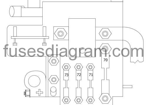
legend.
| Fuse | Amps | Circuits protected |
|---|---|---|
| 70 | 150A | Fuse and relay box in engine compartment |
| 71 | 70A | Fuse and relay box in passenger compartment |
| 72 | 50A | Electric heating system, PTC 2 |
| 73 | 60A | Preheating control unit Automatic transmission (30A also used) |
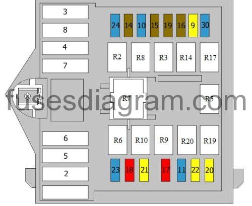
Fuse box in engine compartment Alfa Romeo Brera.
Fuse box location.
Fuse box near the battery. To gain access to the fuses, loosen the two fastening screws A and remove the protection cover B.
fuse box diagram.
legend.
| Fuse | Amps | Circuits protected |
|---|---|---|
| 1 | 70A | Fuse and relay box in passenger compartment Fuse and relay box in luggage compartment (60A also used) |
| 2 | 40A | Climate control fan (50A also used) |
| 3 | 20A | Electric steering lock |
| 4 | 40A | Brake system |
| 5 | 40A | Brake system VDC (20A also used) |
| 6 | 40A | Cooling fan 1 (50A also used) |
| 7 | 50A | Cooling fan 2 |
| 8 | 30A | Electric heating system, PTC 1 Or Gearbox pump |
| 9 | 20A | Headlight washer |
| 10 | 15A | Horns |
| 11 | 15A | Injection system, secondary services |
| 14 | 7,5A | Right main beam |
| 15 | 7,5A | Left main beam |
| 16 | 7,5A | Injection system |
| 17 | 10A | Injection system, primary services |
| 18 | 10A | Injection control unit CAE control unit (automatic transmission) Automatic gearbox |
| 19 | 7,5A | Compressor |
| 20 | 20A | Telephone control |
| 21 | 20A | Fuel pump |
| 22 | 20A | Ignition coils Injectors |
| 23 | 15A | Radio Navigation system |
| 24 | 15A | CAE control unit (automatic transmission) Automatic gearbox |
| 30 | 15A | Fog light |
| R2 | Main beam relay Headlight relay | |
| R3 | Horn relay | |
| R5 | Compressor clutch relay | |
| R6 | Cooling fan, low-speed relay | |
| R7 | Cooling fan, high-speed relay | |
| R8 | Optional equipment | |
| R9 | Injection relay | |
| R10 | Fuel pump relay | |
| R14 | Fog light relay | |
| R17 | Headlight washer relay | |
| R19 | Telephone relay | |
| R20 | Reversing light relay Shift lock relay |
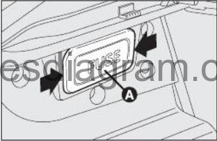
Fuse box in the boot.
To gain access to the fuses, remove the cover A as shown by the arrow.
fuse box diagrmam.
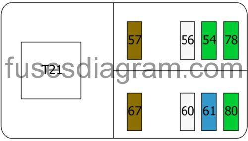
legend.
| Fuse | Amps | Circuits protected |
|---|---|---|
| 54 | 30A | Hi-Fi amplifier |
| 56 | 25A | Driver’s seat adjustment |
| 57 | 7,5A | Heated driver’s seat |
| 60 | 25A | Passenger’s seat adjustment |
| 61 | 15A | Amplifier |
| 67 | 7,5A | Heated passenger’s seat |
| 78 | 30A | Window(s), left side |
| 80 | 30A | Right window(s) |
| T21 | Heated seat(s) relay Seat adjustment relay |