For the Cadilac Catera 1994, 1995, 1996, 1997, 1998, 1999, 2000, 2001 model year.
Fuse box in passenger compartment.
fuse box location.
Instrument panel fuse block is located on lower left hand side of the steering column, mounted to the lower instrument panel.
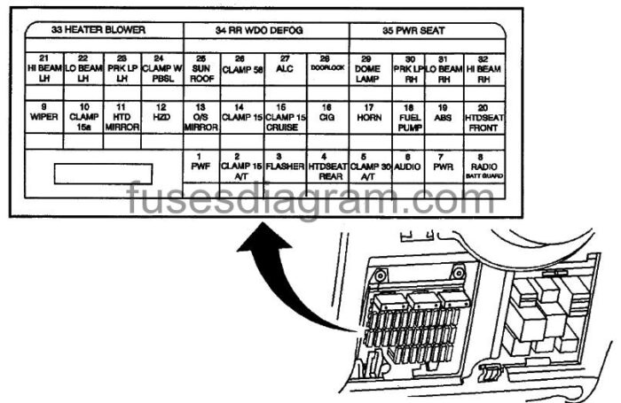
fuse box diagram.
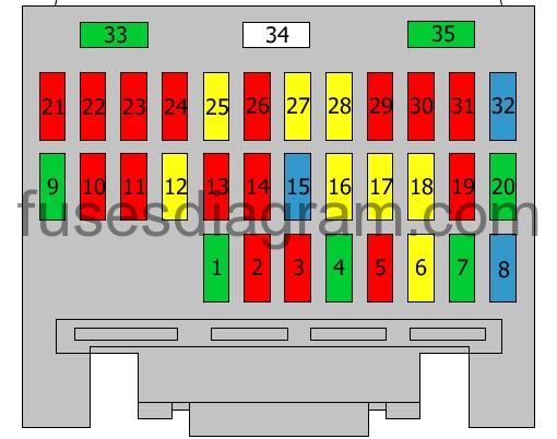
legend.
| Fuses | Amps | Circuits protected |
|---|---|---|
| 1 | 30A | Front power windows Driver’s power window switch Passenger’s power window switch |
| 2 | 10A | Brake light switch |
| 3 | 10A | Transaxle range switch Automatic transmission control unit Power steering control unit Hazard warning switch |
| 4 | 30A | Heated rear seats Rear windscreen sunshade |
| 5 | 10A | Transmission control unit |
| 6 | 20A | Audio amplifier |
| 7 | 30A | Rear power windows |
| 8 | 15A | Headlight switch Direction indicator switch Horn CD changer Multifunction relay |
| 9 | 30A | Windscreen wash/wipe system |
| 10 | 10A | Body control unit Heater system Coolant pump |
| 11 | 10A | Electric mirrors Heater Air-conditioning controls |
| 12 | 20A | Hazard warning switch Instrument panel Brake light switch Data link connector Heater Air-conditioning controls |
| 13 | 10A | Electric mirror controls Remote control Air-conditioning compressor relay Cooling fan test connector Air-conditioning switch |
| 14 | 10A | Telephone Windscreen washer(s) Front heated seats Heater Air-conditioning controls Heated mirrors Heated rear windscreen |
| 15 | 15 | Front heated seats Multifunction relay Suspension system Compressor Instrument panel Headlight switch Cruise control unit Cruise control switch |
| 16 | 20A | Cigarette lighter(s) |
| 17 | 20A | Horns |
| 18 | 20A | Fuel pump |
| 19 | 10A | ABS Traction control unit |
| 20 | 30A | Front heated seats |
| 21 | 10A | Left main beam Daylight running system relay |
| 22 | 10A | Right dipped beam Headlight switch |
| 23 | 10A | Left parking light Direction indicators, left side Left brake light Rear left sidelights Multifunction relay |
| 24 | 10A | Lifting magnet Body control unit Instrument panel |
| 25 | 20A | Sunroof |
| 26 | 10A | Headlight switch Front sidelights Tail light Number plate light(s) Audio system Clock Automatic transmission control unit Heater Air-conditioning controls |
| 27 | 20A | Suspension system Compressor Electronic level control |
| 28 | 20A | Door control receiver Door lock relay |
| 29 | 10A | Interior light(s) Multifunction relay |
| 30 | 10A | Rear right sidelights Right parking light Direction indicators, right side Right brake light |
| 31 | 10A | Right dipped beam Direction indicator switch |
| 32 | 15A | Right main beam |
| 33 | 30A | Air-conditioning compressor relay Blower control |
| 34 | 40A | Heated mirror(s) Heated rear windscreen |
| 35 | 30A | Electric seat control |
Relay box №1 in passenger compartment Cadilac Catera.
Relay’s blocks are located under driver’s side of instrument panel.
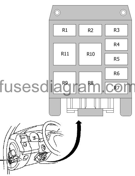
legend.
Relay R1 – Daylight running system relay
Relay R2 – Suspension
Air compressor relay
Relay R3 – Parking light relay
Relay R4 – Dipped beam relay
Relay R5 – Not used
Relay R6 – Not used
Relay R7 – Left main beam
Relay R8 – Horn relay
Relay R9 – Right main beam
Relay R10 – Direction indicator flasher
Relay R11 – Heated mirror relay
Heated rear windscreen relay
Relay box №2 in passenger compartment.

legend.
Relay R1 – Relay, heated front seats
Passenger’s seat
Relay R2 – Relay, heated front seats
Driver’s seat
Relay R3 – Power steering control unit
Relay R4 – Multifunction relay
Fuse box in engine compartment, near the battery.
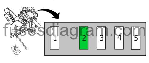
Fuse 1 (80.0 A) – ABS, Body control unit
Fuse 2 (30.0 A) – No information is available
Fuse 3 (80.0 A) – Ignition switch
Fuse 4 (80.0 A) – Relay box in engine compartment
Fuse 5 (80.0 A) – Relay box in engine compartment
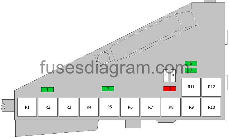
ECM housing in engine comparmtent.
ECM housing is located on driver’s front corner of engine comparment.
fuse box layout.
| Fuses | Amps | Circuits protected |
|---|---|---|
| 1 | 30A | Cooling fan 2 |
| 2 | 30A | Cooling fan 1 |
| 3 | 10A | Cooling fan 1 Engine control unit Blower |
| 4 | 40A | Cooling fan control |
| 5 | 50A | Secondary air injection pump |
| 6 | 30A | Engine control unit |
| 7 | 30A | No information is available |
| R1 | Secondary air injection pump relay | |
| R2 | Cooling fan relay | |
| R3 | Additional heater Coolant pump | |
| R4 | Windscreen wiper relay(s) | |
| R5 | Air-conditioning compressor relay Or Horn | |
| R6 | Cooling fan relay | |
| R7 | Cooling fan relay | |
| R8 | Cooling fan relay | |
| R9 | Cooling fan relay | |
| R10 | Engine control relay | |
| R11 | Cooling fan relay | |
| R12 | Fuel pump relay Additional relay, fuel pump |