For the Audi A6 (C7) (4G) 2011, 2012, 2013, 2014, 2015, 2016, 2017 model year.
| Cigarette lighter fuse – (fuse box in luggage compartment, fuse №15/20A and fuse №16/20A) |
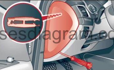
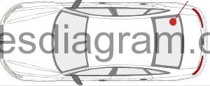
Fuse box in passenger compartment.
fuse box location.
The fuses are located at the front left and right of the cockpit.
Driver side of the cockpit: fuse panel cover.
fuse box diagram.
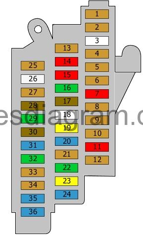
legend.
| Fuse | Amps | Circuits Protected |
|---|---|---|
| 1 | 5A | TCS/ESP button Control unit for the air quality improvement system Power steering control unit Heated seat control unit Trailer detection control unit Electric parking brake Passenger’s side airbag deactivation light |
| 2 | 5A | Automatic anti-dazzle rear-view mirror |
| 3 | Not used | |
| 4 | 5A | Control unit |
| 5 | 5A | ABS control unit |
| 6 | 5A | Air quality sensor Refrigerant pressure and temperature sensor Humidity sender |
| 7 | 10A | Adaptive cruise control unit |
| 8 | 5A | Airbag control unit Seat occupied recognition control unit |
| 9 | 5A | Data bus diagnostic interface |
| 10 | 5A | Garage door operation control unit Night vision system control unit Or Garage door operation control unit Night vision system control unit Control unit for sound transmitted through the vehicle body structure |
| 11 | 10A | Camera control unit |
| 12 | 5A | Active steering control unit |
| 13 | 5A | Data bus diagnostic interface |
| 14 | 10A | Air-conditioning control unit |
| 15 | 10A | ABS control unit |
| 16 | 30A | Driver’s door control unit |
| 17 | 7,5A | Front passenger’s seat adjustment |
| 18 | 35A | Active steering control unit |
| 19 | 20A | Sliding roof |
| 20 | 15A | Rear left door control unit |
| 21 | 5A | Front passenger’s seat adjustment switch |
| 22 | 30A | Additional heater control unit |
| 23 | 20A | Sliding roof or not used |
| 24 | 15A | Driver’s door control unit or not used |
| 25 | 5A | Clutch pedal position sensor |
| 26 | 25A | Fuel pump control unit |
| 27 | 5A | Brake light switch Brake pedal position sensor |
| 28 | 7,5A | Exhaust gas flap control unit Exhaust gas flap control unit 2 Or Reductant control unit (5A also used) or not used |
| 29 | 30A | Rear left door control unit |
| 30 | 7,5A | Driver’s seat adjustment |
| 31 | 15A | Horns Horn relay |
| 32 | 30A | Wiper control unit Wiper motor |
| 33 | 5A | Rain and light sensor |
| 34 | 5A | Driver’s seat adjustment switch |
| 35 | 15A | Front passenger’s door control unit |
| 36 | 15A | Control unit, rear right door |
| 37 | 15A | Fuse and relay box in luggage compartment |
| 38 | 30A | Fuse box No. 2 in passenger compartment |
| 39 | 15A | Fuse and relay box in engine compartment, fuses 3, 12, 13 |
| 40 | 40A | Engine control unit Starter motor relay Starter motor, secondary relay |
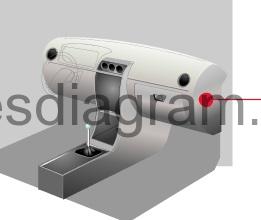
Front passenger side cockpit: fuse panel with plastic bracket.
fuse box diagram
legend.
| Fuse | Amps | Circuits protected |
|---|---|---|
| 1 | 5A | Head-up display control unit |
| 2 | 5A | Vehicle information control unit |
| 3 | 5A | CD changer DVD |
| 4 | 7,5A | Information display control unit Multimedia control unit |
| 5 | 5A | Chip card reader Traffic Message Channel (TMC) antenna |
| 6 | 5A | Control panel control unit |
| 7 | 5A | Control unit, steering column electronics |
| 8 | 7,5A | Headlight range control unit Power output control unit for the headlight |
| 9 | Not used | |
| 10 | 7,5A | Power output control unit for the headlight |
| 11 | Not used | |
| 12 | Not used | |
| 13 | 10A | Climatronic control unit |
| 14 | 40A | Fresh-air blower control unit |
| 15 | 10A | Diagnostic connector (16) |
| 16 | 5A | Immobiliser |
| 17 | 5A | Steering column lock control unit |
| 18 | 10A | Control unit, steering column electronics |
| 19 | 25A | Steering column adjustment control unit |
| 20 | 5A | Lighting switch |
| 21 | Not used | |
| 22 | Not used | |
| 23 | Not used | |
| 24 | Not used |
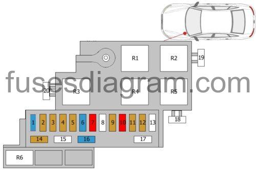
Fuse and relay box №1 in engine compartment.
fuse box diagram.
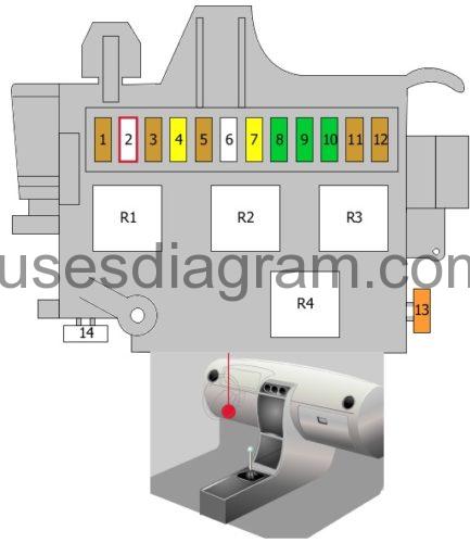
legend.
| Fuse | Amps | Circuitd protected |
|---|---|---|
| 1 | 5 | Terminal 15 voltage supply relay |
| 2 | Not used | |
| 3 | 5 | Control unit |
| 4 | 20 | ABS control unit |
| 5 | 5 | Security alarm system |
| 6 | 35 | Power supply control unit |
| 7 | 20 | Power supply control unit |
| 8 | 30 | Power supply control unit |
| 9 | 30 | Power supply control unit |
| 10 | 30 | Power supply control unit |
| 11 | 5 | Front interior light(s) Control unit, roof electronics |
| 12 | 5 | Additional heater remote control receiver |
| 13 | 40 | ABS control unit |
| 14 | Not used | |
| R1 | Horn relay Or Automatic anti-dazzle rear-view mirror | |
| R2 | Terminal 15 voltage supply relay | |
| R3 | Vacuum pump relay or not used | |
| R4 | Not used |
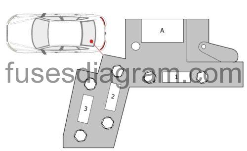
Fuse and relay box №2 in passenger compartment.
fuse box diagram.
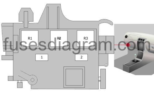
legend.
Fuse 1 (40.0 A) – Heating element(s)
Fuse 2 (60.0 A) – Heating element(s)
Relay R1 – Low-output heating relay
Relay R2 – High-output heating relay
Relay R3 – Additional air heater control unit or not used
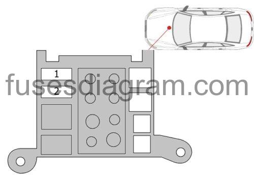
Additional fuse in passenger compartment.
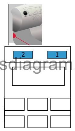
Fuse 1 (15.0 A) – Seat adjustment
Fuse 2 (15.0 A) – Passenger’s seat adjustment
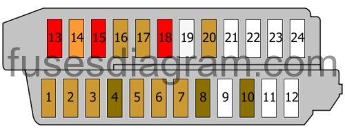
Fuse and relay box in luggage compartment.
fuse box location.
The fuses are located of the behind the trim on the right side of the luggage compartment.
fuse box diagram.
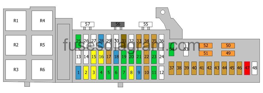
legend.
| Fuse | Amps | Circuits protected |
|---|---|---|
| 1 | 15A | Trailer detection control unit |
| 2 | 20A | Trailer detection control unit |
| 3 | 20A | Trailer detection control unit |
| 4 | 30A | Handbrake control unit |
| 5 | 30A | Handbrake control unit |
| 6 | 30A | Front passenger’s door control unit |
| 7 | 30A | Comfort system control unit |
| 8 | 20A | Comfort system control unit |
| 9 | 15A | Seat ventilation |
| 10 | 5A | Connector |
| 11 | 30A | Air-conditioning control unit Heated seat control unit |
| 12 | Not used | |
| 13 | 25A | Seat belt pretensioner |
| 14 | 25A | Seat belt pretensioner |
| 15 | 20A | Cigarette lighter 12V socket DC-AC converter with socket, 12V – 230V |
| 16 | 20A | Rear cigarette lighter Additional 12V sockets |
| 17 | 5A | Electric parking brake |
| 18 | 15A | Adaptive suspension control unit |
| 19 | 30A | Control unit, rear right door |
| 20 | 30A | Comfort system control unit |
| 21 | 30A | Control unit |
| 22 | 5A | Telephone Aerial selection control unit |
| 23 | 30A | Digital sound package control unit |
| 24 | Not used | |
| 25 | 30A | Digital sound package control unit Information display control unit Radio (20A also used) |
| 26 | 5A | Fuel tank leakage control unit |
| 27 | Not used | |
| 28 | 15A | Engine mount control unit Reductant control unit Or Reductant control unit or not used |
| 29 | Not used | |
| 30 | Not used | |
| 31 | 7,5A | Radio |
| 32 | A | Multimedia control unit Information display control unit Information display |
| 33 | 5A | Automatic anti-dazzle rear-view mirror |
| 34 | 5A | Rear-view camera system |
| 35 | 5A | TV tuner |
| 36 | Not used | |
| 37 | 5A | Terminal 15 voltage supply relay |
| 38 | 5A | Handbrake control unit |
| 39 | 5A | Adaptive suspension control unit |
| 40 | 5A | Comfort system control unit Selector lever control unit Clutch pedal position sensor |
| 41 | 5A | Parking assistance control unit |
| 42 | 5A | Connector |
| 43 | 5A | Voltage regulator(s) |
| 44 | 5A | Lane change assist control unit |
| 45 | 5A | Diagnostic connector (16) Power supply control unit |
| 46 | 5A | 4WD control unit |
| 47 | 10A | Windscreen wiper motor or not used |
| 48 | Not used | |
| 49 | 40A | Adaptive suspension compressor relay |
| 50 | 40A | Voltage regulator(s) |
| 51 | 40A | Heated rear windscreen relay |
| 52 | 40A | Voltage regulator(s) |
| 53 | 35A | 4WD control unit |
| 54 | 30A | Reductant metering system relay or not used |
| 55 | Not used | |
| 56 | 1A | Control unit or not used |
| 57 | Not used | |
| R1 | Not used | |
| R2 | Heated rear windscreen relay | |
| R3 | Power socket relay | |
| R4 | Terminal 15 voltage supply relay | |
| R5 | Adaptive suspension compressor relay | |
| R6 | Reductant metering system relay Or Cooling fan relay or not used |
Main fuse box in luggage compartment.
Fuse 1 (150.0 A) – Main fuse
Fuse 2 (150.0 A) – Main fuse (110A also used)
Fuse 3 (150.0 A) – Main fuse
A – Battery isolation/igniter
Fuse and relay box in engine compartment.
fuse box diagram.
legend.
| Fuse | Amps | Circuits protected |
|---|---|---|
| 1 | 15A | Automatic transmission control unit |
| 2 | 5A | Oil level and temperature sensor |
| 3 | 5A | Engine control unit |
| 4 | 5A | Engine control unit |
| 5 | 5A | Mass airflow meter |
| 6 | 15A | Engine control unit |
| 7 | 10A | Fuel metering solenoid Fuel pressure control solenoid |
| 8 | Not used | |
| 9 | 5A | Voltage regulator(s) Engine control unit |
| 10 | 10A | Oxygen sensor in front of the catalytic converter |
| 11 | 5A | Cooling fan control unit Cooling fan control unit 2 |
| 12 | 5A | Automatic transmission control unit |
| 13 | Not used | |
| 14 | 5A | Exhaust gas recirculation coolant pump |
| 15 | Not used | |
| 16 | 15A | Low-output heating relay High-output heating relay Left electro-hydraulic engine mounting solenoid Right electro-hydraulic engine mounting solenoid Exhaust gas cooler solenoid Turbo pressure control solenoid Crankcase breather heater |
| 17 | Not used | |
| 18 | Not used | |
| 19 | 80A | Glow plug |
| 20 | Not used | |
| R1 | Not used | |
| R2 | Starter motor relay Starter motor, secondary relay | |
| R3 | Glow plug control unit | |
| R4 | Terminal 30 voltage supply relay | |
| R5 | Not used | |
| R6 | Not used |
Additional fuses in engine compartment.
Fuse 1 (40.0 A) – Radiator
(60A also used)
(80A also used)
Fuse 2 (40.0 A) – Radiator
(60A also used)
(80A also used)