For the BMW 7 (E65, E66, E68) 2001, 2002, 2003, 2004, 2005, 2006, 2007, 2008 model year.
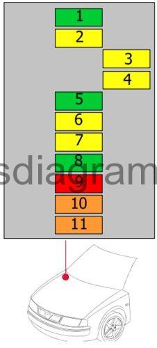
Fuse box in glove compartment.
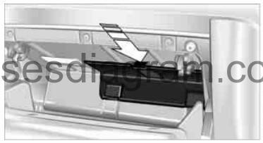
Press the tab on the cover to the front, then fold up the cover.
fuse box diagram.
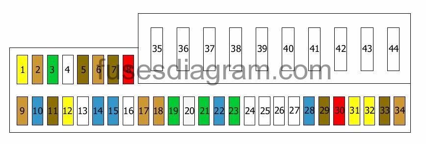
legend.
| Fuse | Amps | Circuits Protected |
|---|---|---|
| 1 | 20A | Auxiliary heating system |
| 2 | 5A | Antenna |
| 3 | 30A | Body control unit |
| 4 | Not used | |
| 5 | 7,5A | Centre console unit Information display Rear information display Telephone |
| 6 | 5A | CD changer |
| 7 | 7,5A | Cruise control unit |
| 8 | 10A | Dynamic drive |
| 9 | 5A | Tyre pressure control unit (RDC) |
| 10 | 15A | Air-conditioning control unit |
| 11 | 7,5A | Rear information display |
| 12 | 20A | Steering column switches |
| 13 | Not used | |
| 14 | 15A | Power save relay |
| 15 | 15A | Safety and gateway module Driver’s seat Passenger’s seat |
| 16 | Not used | |
| 17 | 5A | Dynamic stability control (DSC) Light switch module |
| 18 | 5A | Headlight(s) |
| 19 | 30A | Door control unit, rear left |
| 20 | 25A | Dynamic stability control (DSC) |
| 21 | 30A | Door control unit, front left |
| 22 | 15A | Transmission control unit Or Not used |
| 23 | 30A | Driver’s seat control unit |
| 24 | Not used | |
| 25 | Not used | |
| 26 | Not used | |
| 27 | Not used | |
| 28 | 15A | Instrument panel |
| 29 | 7,5A | On-board diagnostic |
| 30 | 10A | Electronics box (E-box) cooling fan Power save relay Fuel heater relay Starter relay |
| 31 | 20A | Front cigarette lighter Rear cigarette lighter |
| 32 | 20A | Rear 12V socket |
| 33 | 7,5A | Instrument panel |
| 34 | 5A | Antenna amplifier |
| 35 | 40A | Wiper motor |
| 36 | 50A | Light module Or Not used |
| 37 | 40A | Blower |
| 38 | Not used | |
| 39 | 50A | Dynamic stability control (DSC) |
| 40 | 60A | Integrated control unit |
| 41 | 50A | Fuel heater relay Or Not used |
| 42 | 50A | Central locking |
| 43 | 50A | Cigarette lighter relay |
| 44 | 50A | Light module Or Not used |
Fuse box in engine compartment.
fuse box diagram (type 1).
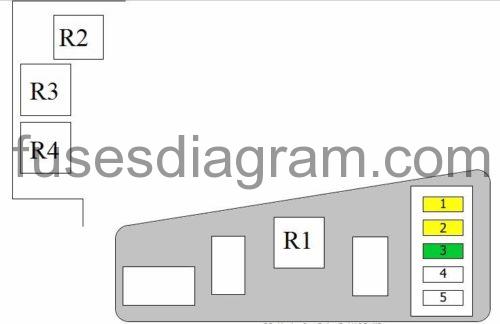
| Fuse | Amps | Circuits Protected |
|---|---|---|
| 1 | 20A | Evaporative canister purge solenoid(s) Mass airflow meter Rail pressure control valve Hall sensor |
| 2 | 20A | Crankcase heater Swirl control valve, solenoid Inlet manifold switch-over valve Oil level sensor Preheating unit |
| 3 | 30A | Battery, B+ DDE control unit |
| 4 | Not used | |
| 5 | Not used | |
| R1 | DDE main relay | |
| R2 | Starter relay | |
| R3 | Not used | |
| R4 | Not used |
fuse box diagram (type 2).
| Fuses | Amps | Circuits protected |
|---|---|---|
| 1 | 30A | Variable valve timing DME Injectors (cylinders 5 – 8) |
| 2 | 20A | Fuel tank cap Camshaft timing solenoid Camshaft sensor |
| 3 | 20A | Ignition coils 1 – 4 |
| 4 | 20A | Ignition coils 5 – 8 |
| 5 | 30A | Camshaft timing solenoid Camshaft sensor MAP-controlled engine cooling thermostat Crankshaft position sensor Mass airflow meter |
| 6 | 20A | Injectors (cylinders 1 – 4) |
| 7 | 20A | Transmission control unit |
| 8 | 30A | Oxygen sensor in front of the catalytic converter Oxygen sensor 2 in front of the catalytic converter Oxygen sensor behind the catalytic converter Oxygen sensor 2 behind the catalytic converter Oil quality sensor |
| 9 | 10A | Fuel tank leak diagnosis Secondary air pump relay Mass airflow meter Electronics box (E-box) cooling fan Exhaust manifold flap Power save relay |
| 10 | 40A | Variable valve timing |
| 11 | 40A | Variable valve timing |
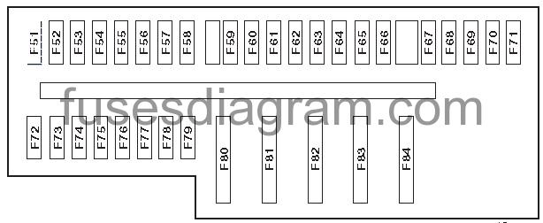
Fuse box in luggage compartment.
fuse box diagram.
legend.
F51 (15A) Heated wind screen relay
F52 (15A) Cool box
F53 (5A)
F54 (5A) Key less entry and start control module
F55 (30A) Seat heater control module,rear
F56 (30A) Electric front seats
F57 (15A)
F58 (30A) Door function control module, right front
F59 (5A) Parking brake control module
F60 (30A) Door function control module, right rear
F61 (30A) Parking brake control module
F62 (30A) Suspension compressor pump
F63 (20A) Sunroof control module
F64 -F65 (30A)
F66 (20A) Trailer socket
F67 (30A)
F68 -F69 -F70 -F71 (5A)
F72 (7,5A) Suspension control module
F73 (15A)
F74 (30A) Trailer control module
F75 (30A)
F76 (10A)
F77 (5A)
F78 (30A)
F79 (10A)
F80 -F81 (50A) Boot lid opening-closingcontrolmoduleF82 -F83 (40A)
F84 –