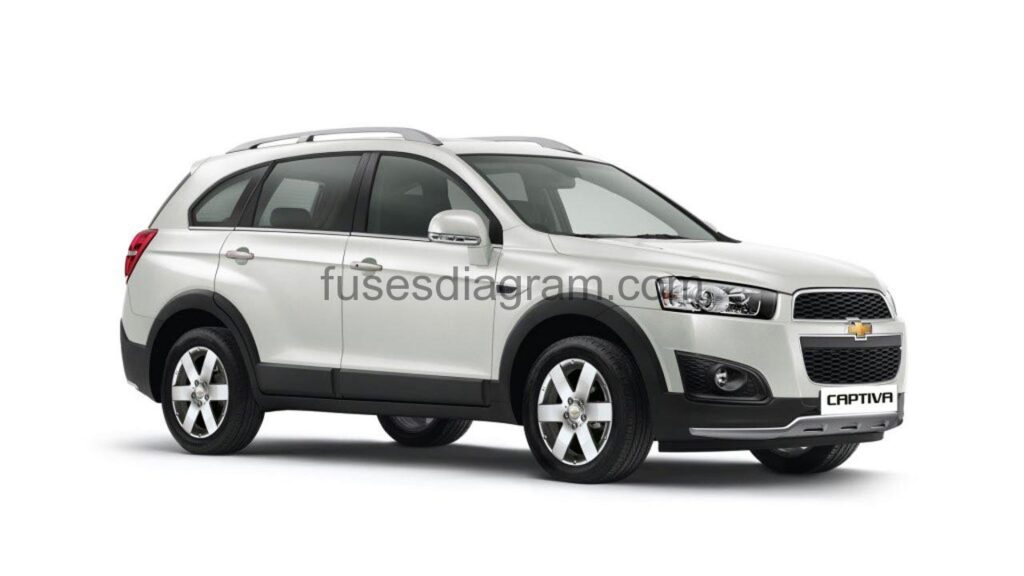
For the Chevrolet Captiva (C140) 2010, 2011, 2012, 2013, 2014, 2015 model year.
Fuse box in passenger compartment.
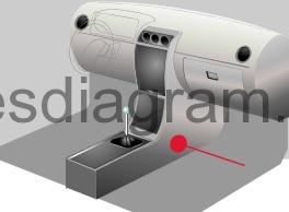
fuse box location.
Interior fuse block is located in the left side of the front passenger foot well.
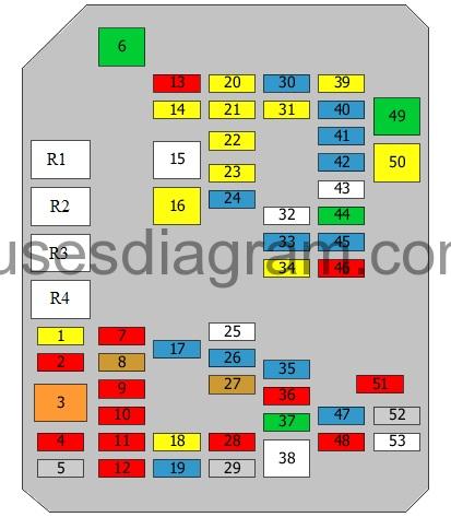
fuse box diagram.
legend.
| Fuses | Amps | Circuits protected |
|---|---|---|
| 1 | 20A | Heated seat switches |
| 2 | 10A | Air quality sensor Heating, ventilation and air conditioning (HVAC) Blower, high-speed relay Additional heater relay 1 |
| 3 | 40A | Blower motor |
| 4 | 10A | Headlight levelling control unit Power steering control unit Left headlight levelling actuator Right headlight levelling actuator |
| 5 | 2A | Multifunction switch Instrument panel Electric rear-view mirror switch |
| 6 | 30A | Driver's seat adjustment switch |
| 7 | 10A | Fuel pump control unit or not used |
| 8 | 5A | Interior mirror Security alarm |
| 9 | 10A | Rear fog light relay Passenger's airbag deactivation light Instrument cluster Information display control unit Multifunction switch Instrument panel |
| 10 | 10A | Airbag diagnostic module |
| 11 | 10A | Body control unit Trailer connector |
| 12 | 10A | Park/neutral position switch |
| 13 | 10A | Sunroof control unit Mirror control unit |
| 14 | 20A | Reversing light relay, trailer Relay, trailer lights |
| 15 | Spare fuse | |
| 16 | 20A | Sunroof control unit |
| 17 | 15A | Differential control unit Canister vent solenoid |
| 18 | 20A | Body control unit Trailer connector |
| 19 | 15A | Radio |
| 20 | 20A | Fuel pump control unit |
| 21 | 20A | Accessory socket |
| 22 | 20A | Front cigarette lighter |
| 23 | 20A | Luggage compartment accessory socket |
| 24 | 15A | Engine control unit Mass airflow meter with air temperature sensor ESP Or Engine control unit Vacuum pump relay ESP |
| 25 | Spare fuse | |
| 26 | 15A | Rear fog light |
| 27 | 5A | Air-conditioning diode |
| 28 | 10A | Instrument cluster |
| 29 | 2A | Steering wheel controls |
| 30 | 15A | Fuel filler flap |
| 31 | 20A | Speaker Subwoofer |
| 32 | Spare fuse | |
| 33 | 15A | Body control unit |
| 34 | 20A | Windscreen washer pump |
| 35 | 15A | Body control unit |
| 36 | 10A | Body control unit |
| 37 | 30A | Trailer connector |
| 38 | Spare fuse | |
| 39 | 20A | Central locking relay |
| 40 | 15A | Body control unit |
| 41 | 15A | Body control unit |
| 42 | 15A | Body control unit |
| 43 | Spare fuse | |
| 44 | 30A | Audio amplifier |
| 45 | 15A | Left daylight running system |
| 46 | 10A | Heated driver's seat control unit Heated passenger's seat control unit |
| 47 | 15A | Immobiliser control unit |
| 48 | 10A | Airbag diagnostic module |
| 49 | 30A | Power windows |
| 50 | 20A | Driver's power window |
| 51 | 10A | Ultrasonic sensor Parking assistance control unit Security alarm Clock Multifunction switch Instrument panel |
| 52 | 2A | Ignition switch |
| 53 | Spare fuse | |
| R1 | Accessory relay | |
| R2 | Auxiliary power relay | |
| R3 | Engine running relay | |
| R4 | Main relay | |
| The following relays are integrated. | ||
| R5 | Windscreen washer pump | |
| R6 | Daylight running system relay | |
| R7 | Rear fog light relay | |
| R8 | Reversing light relay, trailer | |
| R9 | Relay, trailer light | |
| R10 | Relay, trailer light | |
| R11 | Door unlock relay | |
| R12 | Fuel filler flap relay | |
| R13 | Liftgate relay | |
| R14 | Door lock relay | |
| R15 | Driver's door lock relay | |
| R16 | Deadlock relay | |
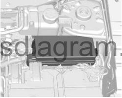
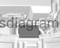
Fuse box in engine compartment.
fuse box diagram.
legend.
| Fuses | Amps | Circuits protected |
|---|---|---|
| 1 | 80A | Cooling fan control unit or not used |
| 2 | 40A | Cooling fan, high-speed relay or not used |
| 3 | 15A | Engine control unit Heated oxygen sensor Fuel pressure regulator EGR cooling bypass valve Or Engine control unit Ignition coils |
| 4 | 15A | Inlet manifold valve control motor Or Ignition coils |
| 5 | 30A | Engine control unit Or Engine control unit Additional fuse and relay box in engine compartment |
| 6 | 40A | Cooling fan, high-speed relay or not used |
| 7 | 15A | Engine control unit |
| 8 | 20A | Starter motor |
| 9 | 15A | Canister vent solenoid Heated oxygen sensors Mass airflow meter with air temperature sensor |
| 10 | 60A | Fuse and relay box in passenger compartment |
| 11 | 20A | Electronic brake control unit (EBCM) |
| 12 | Spare fuse | |
| 13 | 15A | ESP |
| 14 | Spare fuse | |
| 15 | ||
| 16 | 10A | Body control unit |
| 17 | 20A | Brake lights Additional brake light |
| 18 | 40A | Parking brake control unit |
| 19 | 25A | Windscreen wiper relay High-/low-speed wiper relay |
| 20 | 10A | Air-conditioning compressor |
| 21 | Spare fuse | |
| 22 | 10A | Rear-view camera system Number plate light Rear left sidelight Rear right sidelight Front left parking light Front left parking light/direction indicator Left tail light Right tail light |
| 23 | 10A | Front right parking light Front right parking light/direction indicator Right tail light Or Front right parking light |
| 24 | 10A | Headlight |
| 25 | 60A | Fuse and relay box in passenger compartment |
| 26 | 20A | Rear wiper motor |
| 27 | 10A | Trailer connector |
| 28 | 20A | Headlight washer pump |
| 29 | 10A | Headlight |
| 30 | 50A | Electronic brake control unit (EBCM) Diagnostic connector |
| 31 | 60A | Fuse and relay box in passenger compartment |
| 32 | 30A | Fuse and relay box in passenger compartment |
| 33 | 15A | Door mirrors |
| 34 | 10A | Front right parking light Front right parking light/direction indicator Right tail light Or Front right parking light |
| 35 | 15A | Front left fog light Front right fog light |
| 36 | 10A | Right headlight, main beam |
| 37 | 10A | Left headlight, main beam |
| 38 | 15A | Horns |
| R1 | Cooling fan, high-speed relay | |
| R2 | Cooling fan control | |
| R3 | Powertrain control unit (PCM) relay | |
| R4 | Cooling fan, high-speed relay | |
| R5 | Starter relay | |
| R6 | Vacuum pump relay Or Fuel pump relay | |
| R7 | Brake light relay | |
| R8 | Windscreen wiper relay | |
| R9 | High-/low-speed wiper relay | |
| R10 | Relay, rear demister | |
| R11 | Headlight washer pump relay | |
| R12 | Headlight relay, main beam | |
| R13 | Headlight relay, dipped beam | |
| R14 | Front fog light relay | |
| R15 | Horn relay | |
| R16 | Parking light relay |
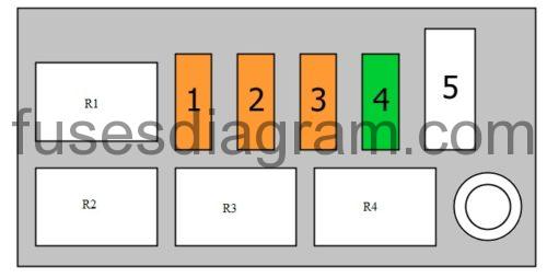
Additional fuse box in engine compartment.
(only diesel).
fuse box diagram.
legend.
| Fuses | Amps | Circuits protected |
|---|---|---|
| 1 | 40A | PTC, relay 3 |
| 2 | 40A | PTC, relay 2 |
| 3 | 40A | PTC, relay 1 |
| 4 | 30A | Fuel filter heater relay |
| 5 | 60A | Glow plug control unit |
| R1 | PTC, relay 3 | |
| R2 | PTC, relay 2 | |
| R3 | PTC, relay 1 | |
| R4 | Fuel filter heater relay |

