For Ford Fiesta (06) 2009, 2010, 2011, 2012, 2013, 2014, 2015, 2016, 2017 model year.
| Cigarette lighter fuse – fuse box in passenger compartment – Fuse F22/20A (Europe) Cigarette lighter fuse – fuse box in passenger compartment – Fuse F33/20A (USA) |
MENU
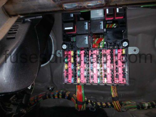
Fuse box in passenger compartment.
- fuse box diagram (Europe type 1 )
- fuse box diagram (Europe type 2 )
- fuse box diagram (Europe since 2012)
- fuse box diagram (USA 2011-2013)
- fuse box diagram (USA 2014-2017)
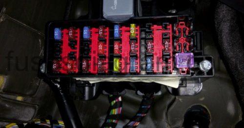
Fuse box in engine compartment.
- fuse box diagram (Europe 2008-2012)
- fuse box diagram (Europe 2012-2017)
- fuse box diagram (USA 2010-2011)
- fuse box diagram (USA 2011-2015)
- fuse box diagram (USA 2015-2017)
Main fuse box in engine compartment.
Fuse box in passenger compartment.
fuse box location.
The fuse panel is located behind the glove box. Open the glove box, press the sides inward and swing the glove box down.
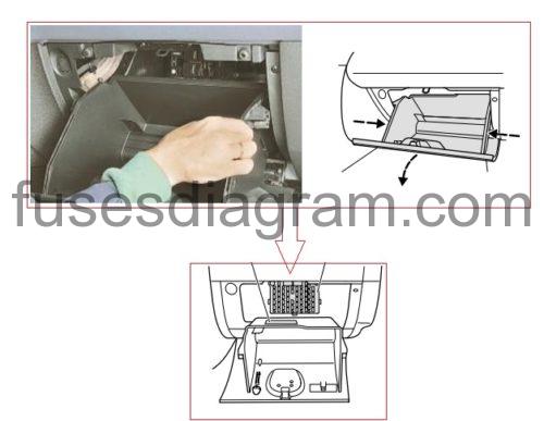
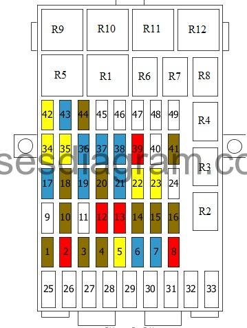
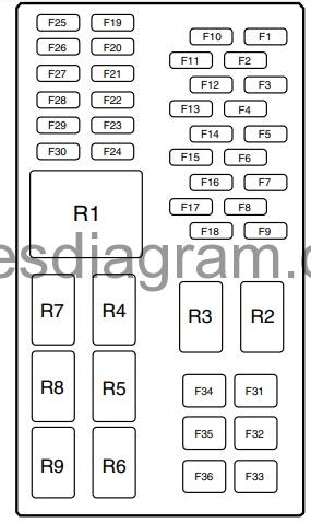
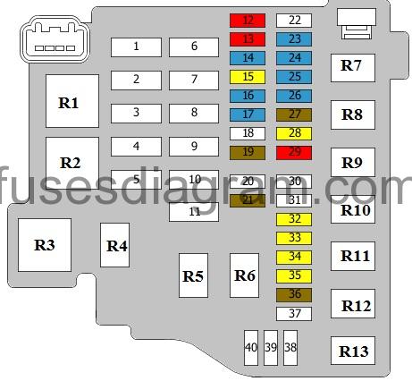
fuse box diagram (Europe type 1).
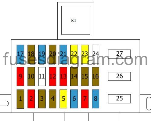
Assignment of the fuses.
| R1 | Ignition relay |
| F1 | (7,5A) Ignition Rain sensor Windscreen heater |
| F2 | (10A) Stop lamps switch |
| F3 | (7,5A) Reversing lamps |
| F4 | (7,5A) Headlamp adjustment |
| F5 | (20A) Windscreen wipers |
| F6 | (15A) Rear wiper Body control unit (BCM) |
| F7 | (10A) Windscreen washers |
| F8 | (15A) Trailer or (10A) Parking assistance |
| F9 | (10A) Parking aid or not used |
| F10 | (7,5A) Heated seats |
| F11 | – |
| F12 | (10A) Supplementary restraint system (SRS) |
| F13 | (10A) Ignition Electronic power steering (EPS) Body control unit (BCM) Engine immobiliser control unit ABS |
| F14 | (7,5A) Engine control unit Accelerator pedal position sensor Fuel pump relay Mechatronic unit for the dual-clutch gearbox |
| F15 | (7,5A) Accessory socket or Audio system, instrument cluster |
| F16 | (7,5A) Heated door mirrors |
| F17 | (15A) Ignition system |
| F18 | (7,5A) Instrument panel |
| F19 | (15A) Data link connector (DLC) |
| F20 | (7,5A) Multifunction display Clock |
| F21 | (15A) Radio Navigation Bluetooth control unit |
| F22 | (20A) Cigarette lighter |
| F23 | (20A) Trailer |
| F24 | – |
| F25 | (30A) Front power windows |
| F26 | not used or Heated windscreen, left side |
| F27 | not used or Heated windscreen, right side |
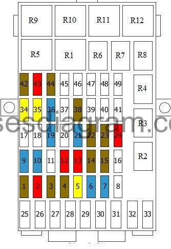
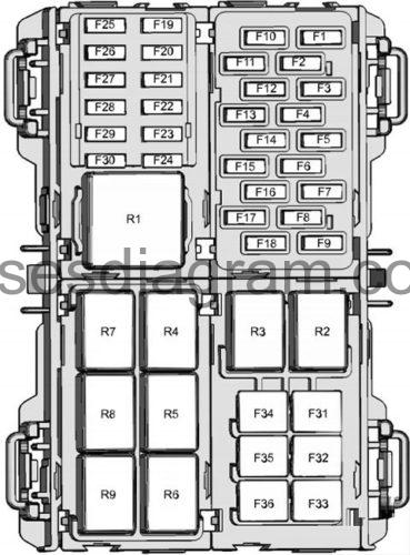
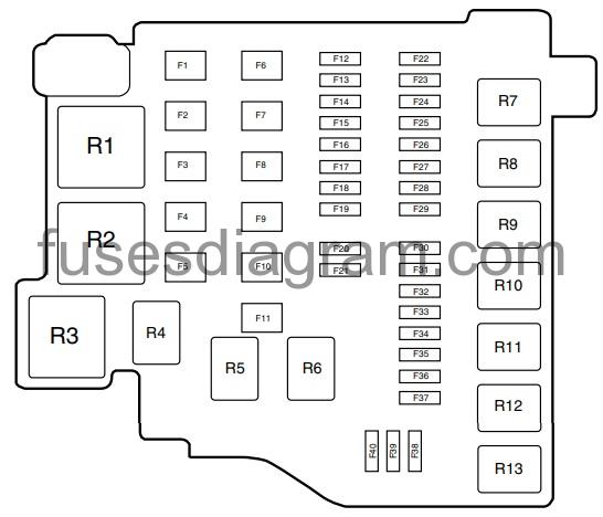
fuse box diagram in passenger compartment (Europe type 2).
legend.
| R1 | Ignition relay |
| R2 | Folding mirror |
| R3 | Folding mirror |
| R4 | – |
| R5 | Heated windscreen relay |
| R6 | Keyless entry control unit |
| R7 | Keyless entry control unit |
| R8 | Battery current saving relay |
| R9 | Coolant pump relay |
| R10 | Heated seat(s) |
| R11 | Heated seat(s) |
| R12 | – |
| F1 | (7.5A) Ignition Rain sensor Windscreen heater |
| F2 | (10A) Stop lamps switch |
| F3 | (7,5A) Reversing lamps |
| F4 | (7,5A) Headlamp adjustment |
| F5 | (20A) Windscreen wipers |
| F6 | (15A) Rear wiper Body control unit (BCM) |
| F7 | (10A) Windscreen washers |
| F8 | (15A) Trailer or (10A) Parking assistance |
| F9 | (10A) Parking aid or not used |
| F10 | (7,5A) Heated seats |
| F11 | – |
| F12 | (10A) Supplementary restraint system (SRS) |
| F13 | (10A) Ignition Electronic power steering (EPS) Body control unit (BCM) Engine immobiliser control unit ABS |
| F14 | (7,5A) Engine control unit Accelerator pedal position sensor Fuel pump relay Mechatronic unit for the dual-clutch gearbox |
| F15 | (7,5A) Accessory socket or Audio system, instrument cluster |
| F16 | (7,5A) Heated door mirrors |
| F17 | (15A) Ignition system |
| F18 | (7,5A) Instrument panel |
| F19 | (15A) Data link connector (DLC) |
| F20 | (7.5A) Multifunction display Clock |
| F21 | (15A) Radio Navigation Bluetooth control unit |
| F22 | (20A) Cigarette lighter |
| F23 | (20A) Trailer |
| F24 | – |
| F25 | (30A) Front power windows |
| F26 | Heated windscreen, left side |
| F27 | Heated windscreen, right side |
| F28 | – |
| F29 | Coolant pump |
| F30 | Cigarette lighter |
| F31 | (30A) Rear windows |
| F32 | (30A) Heated windscreen, left side |
| F33 | (30A) Heated windscreen, right side |
| F34 | (20A) Keyless entry |
| F35 | (20A) Electronic steering column lock Keyless entry control unit |
| F36 | (15A) Rear 12V socket Or Battery saver |
| F37 | (15A) 12V socket in luggage compartment |
| F38 | Selector lever |
| F39 | Additional safety system |
| F40 | – |
| F41 | Micro-power module Generator |
| F42 | (20A) Sunroof |
| F43 | Door lock Or Tailgate lock |
| F44 | Micro-power module Generator |
| F45 | – |
| F46 | – |
| F47 | – |
| F48 | – |
| F49 | – |
fuse box diagram in passenger compartment (Europe since 2012).
legend.
| R1 | Ignition relay |
| R2 | Power socket relay |
| R3 | Not used |
| R4 | Active Stop system relay |
| R5 | Not used |
| R6 | Keyless entry control unit |
| R7 | Keyless entry control unit |
| R8 | Battery saver |
| R9 | Not used |
| R10 | Not used |
| R11 | Not used |
| R12 | Not used |
| F1 | (7.5A)Windscreen heater Additional heater relay Compressor clutch relay Front interior light Rain sensor Anti-dazzle rear-view mirror Power socket relay |
| F2 | (10A) Stop switch Active Stop system relay |
| F3 | (7,5A) Reversing lamps |
| F4 | (7,5A) Headlamp adjustment |
| F5 | (20A) Windscreen wipers |
| F6 | (15A) Body control unit (BCM) |
| F7 | (15A) Washer pump Windscreen wiper |
| F8 | Not used |
| F9 | (15A) Electric front passenger’s seat |
| F10 | (15A) Electric driver’s seat |
| F11 | – |
| F12 | (10A) Supplementary restraint system (SRS) |
| F13 | (10A) Electronic power steering (EPS) Body control unit (BCM) Engine immobiliser control unit ABS Manual air conditioning Blower motor relay Instrument cluster |
| F14 | (7,5A) Engine control unit Accelerator pedal position sensor Fuel pump relay Mechatronic unit for the dual-clutch gearbox Front fog light relay |
| F15 | (7,5A) Instrument cluster Audio unit |
| F16 | Not used |
| F17 | Not used |
| F18 | Not used |
| F19 | (15A) Data link connector (DLC) |
| F20 | Not used |
| F21 | (15A) Radio Navigation Bluetooth control unit |
| F22 | (7.5A) Instrument cluster |
| F23 | (7.5A) Automatic air-conditioning control unit Manual air-conditioning module System interface control unit Remote control receiver Driver’s power window switch |
| F24 | GPS control unit Navigation and multimedia unit |
| F25 | Not used |
| F26 | Heated windscreen, left side |
| F27 | Heated windscreen, right side |
| F28 | (30A) DC-DC converter Fuse and relay box in passenger compartment, fuses 18, 19, 21, 23, 24 |
| F29 | (20A) Battery saver relay Auxiliary power point |
| F30 | (20A) Cigarette lighter Power socket relay |
| F31 | Not used |
| F32 | Not used |
| F33 | Not used |
| F34 | (20A) Keyless entry |
| F35 | (20A) Keyless entry control unit |
| F36 | (15A) Ignition switch Keyless entry relay |
| F37 | Not used |
| F38 | Alarm sensors 7.5 A |
| F39 | Not used |
| F40 | – |
| F41 | – |
| F42 | (7.5A) Rear-view camera system |
| F43 | (10A) Active Stop system |
| F44 | Passenger’s airbag deactivation light 7.5 A |
| F45 | – |
| F46 | – |
| F47 | – |
| F48 | – |
| F49 | – |
Fuse box diagram in passenger compartment (USA 2011-2013).
legend.
| Fuse/Relay Location | Fuse Amp Rating | Protected circuits |
|---|---|---|
| F1 | 15A | Ignition switch, Keyless entry ignition relay, Keyless entry accessory relay |
| F2 | 10A | Electronic mirror, A/C clutch, Engine compartment fuse panel |
| F3 | 7.5A | Instrument cluster |
| F4 | 7.5A | Passenger airbag deactivation indicator, Occupant classification system |
| F5 | 15A | Diagnostic connector |
| F6 | 10A | Backup lamp |
| F7 | 7.5A | Instrument panel display, Intelligent access (IA) antenna, Manual climate controls |
| F8 | — | Not used |
| F9 | 20A | Keyless vehicle module |
| F10 | 15A | Radio, SYNC® module |
| F11 | 20A | Front wipers, Body control module (BCM) |
| F12 | 20A | Tire pressure monitoring system (TPMS) |
| F13 | 15A | Rear wiper, BCM |
| F14 | 20A | IA module |
| F15 | 15A | Washer pump |
| F16 | 15A | Global positioning system (GPS) module |
| F17 | 7.5A | Heated seat relay |
| F18 | 10A | Stop lamps, Turn signals |
| F19 | 7.5A | Radio, Instrument cluster |
| F20 | 10A | Airbag module |
| F21 | 10A | BCM, Climate control, Passive anti-theft system transceiver, Electronic power steering module, Instrument cluster, Engine compartment fuse panel |
| F22 | 7.5A | Accelerator pedal position sensor, Powertrain control module (PCM), Gear shifter, Anti-lock brake system (ABS) ignition feed |
| F23 | 10A | Transmission control unit ignition feed, TPMS ignition feed |
| F24 | 7.5A | Front dome lamp, Moon roof switch |
| F25 | 7.5A | Exterior mirrors |
| F26 | 7.5A | TPMS |
| F27 | — | Not used |
| F28 | — | Not used |
| F29 | — | Not used |
| F30 | — | Not used |
| F31 | 30A | Driver and rear power window switches |
| F32 | 20A | Passenger compartment fuse panel battery saver relay |
| F33 | 20A | Power points, Cigarette lighter |
| F34 | 30A | Driver and passenger power window switches |
| F35 | 20A | Moon roof |
| F36 | — | Not used |
| R1 | — | Ignition relay |
| R2 | — | Left rear stop/turn lamp relay |
| R3 | — | Right rear stop/turn lamp relay |
| R4 | — | Driver heated seat relay |
| R5 | — | Passenger heated seat relay |
| R6 | — | IA module – accessory relay |
| R7 | — | IA module – ignition relay |
| R8 | — | Battery saver relay |
| R9 | — | Not used |
Fuse box diagram in passenger compartment (USA 2014-2017).
legend.
| № | Amp Rating | Circuits protected |
|---|---|---|
| 1 | 15 A | Ignition switch |
| 2 | 75 A | Interior mirror, autowipers, heater relay control |
| 3 | 75 A | Instrument cluster |
| 4 | 75 A | Passenger airbag deactivation indicator, passenger sensing system |
| 5 | 15 A | On-board diagnostics connector |
| 6 | 10 A | Reversing lamps |
| 7 | 7.5 A | Instrument panel, information and entertainment display |
| 8 | 7.5 A | Moonroof |
| 9 | 20 A | Keyless entry, keyless starting |
| 10 | 15 A | Audio unit, SYNC |
| 11 | 20 A | Windshield wipers |
| 12 | 7.5 A | Climate control |
| 13 | 15 A | Rear window wiper |
| 14 | 20 A | Keyless entry, keyless starting |
| 15 | 15 A | Wiper switch |
| 16 | 5 A | Electric exterior mirrors, power windows |
| 17 | 15 A | Heated seats |
| 18 | 10 A | Brake lamp |
| 19 | 7.5 A | Instrument cluster |
| 20 | 10 A | Airbags |
| 21 | 7.5 A | Electronic power assisted steering, instrument cluster, ignition, wipers, passive anti-theft system |
| 22 | 7.5 A | Transmission control unit, powertrain control module, anti-lock braking system, electronic stability program Accelorator position sensor (2017) |
| 23 | 7.5 A | Transmission control unit |
| 24 | 7.5 A | Audio unit |
| 25 | 7.5 A | Electric exterior mirrors |
| 26 | 7.5 A | Locking and unlocking, Central locking system |
| 27 | – | Not used |
| 28 | – | Not used |
| 29 | – | Not used |
| 30 | – | Not used |
| 31 | 30 A | Power windows |
| 32 | 20 A | Battery back-up sounder |
| 33 | 20 A | Auxiliary power points, Cigarette lighter |
| 34 | 30 A | Power windows |
| 35 | 20 A | Moonroof |
| 36 | – | Not used |
| Relay: | ||
| R1 | Ignition relay | |
| R2 | Not used | |
| R3 | Not used | |
| R4 | Driver heated seat | |
| R5 | Passenger heated seat | |
| R6 | Keyless starting | |
| R7 | Keyless starting | |
| R8 | Battery back-up sounder | |
| R9 | Accessory delay |
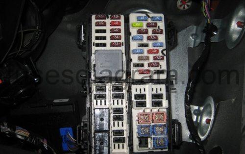
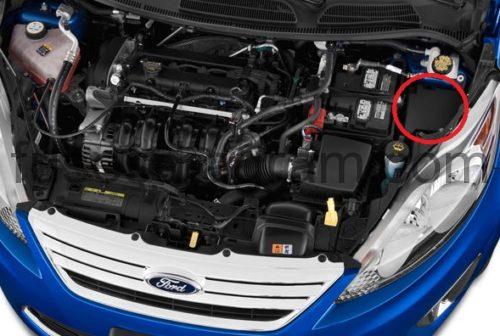
Fuse box in engine compartment.
fuse box location.
fuse box diagram (Europe 2008-2012).
legend.
Fuse 1
ESP control unit
ABS control unit
(30A also used)
40.0 A
Fuse 2
Cooling fan
60.0 A
Fuse 3
Cooling fan
(30A also used)
40.0 A
Fuse 4
Heater blower
30.0 A
Fuse 5
Fuse and relay box in passenger compartment
60.0 A
Fuse 6
Body control unit
Central locking
30.0 A
Fuse 7
Fuse and relay box in passenger compartment
Ignition relay
60.0 A
Fuse 8
Glow plug system
60.0 A
Fuse 9
Windscreen heater
60.0 A
Fuse 10
Mechatronic unit for the dual-clutch gearbox
60.0 A
Fuse 11
Starter relay
30.0 A
Fuse 12
Left main beam
10.0 A
Fuse 13
Right main beam
10.0 A
Fuse 14
Left dipped beam
10.0 A
Fuse 15
Right dipped beam
10.0 A
Fuse 16
Cooling fan
Fuel injector(s)
Variable valve timing
Canister purge solenoid
Mass airflow meter with air temperature sensor
Engine control unit
15.0 A
Fuse 17
Oxygen sensor in front of the catalytic converter
Oxygen sensor behind the catalytic converter
15.0 A
Fuse 18
Transmission control unit
Transmission range sensor
10.0 A
Fuse 19
Not used
Fuse 20
Not used
Fuse 21
Not used
Fuse 22
Exterior lights
Body control unit
15.0 A
Fuse 23
Front fog light(s)
15.0 A
Fuse 24
Direction indicator
Body control unit
15.0 A
Fuse 25
Daylight running system
10.0 A
Fuse 26
Fuse and relay box in passenger compartment
Electric mirror switch
Power window switches
7.5 A
Fuse 27
Engine control unit
Automatic transmission
7.5 A
Fuse 28
ABS control unit
Or
ESP control unit
20.0 A
Fuse 29
Air conditioning
10.0 A
Fuse 30
Micro-power module
Generator
20.0 A
Fuse 31
Generator
7.5 A
Fuse 32
Horn
Battery saver
Body control unit
20.0 A
Fuse 33
Heated rear windscreen
20.0 A
Fuse 34
Fuel pump relay
Diesel fuel heater
20.0 A
Fuse 35
Door lock
20.0 A
Fuse 36
Tailgate lock
20.0 A
Fuse 37
Not used
Fuse 38
Not used
Fuse 39
Not used
Fuse 40
Not used
Relay R1
Cooling fan relay
Relay R2
Glow plug
Relay R3
Engine control unit relay
Relay R4
Main beam relay
Relay R5
Dipped beam relay
Relay R6
Daylight running system relay
Relay R7
Cooling fan relay
Relay R8
Start inhibitor
Relay R9
Air conditioning
Compressor on/off
Relay R10
Front fog light relay
Relay R11
Fuel pump relay
Additional relay, fuel pump
Relay R12
Reversing light relay
Relay R13
Heater blower
Fuse box diagram (Europe 2012-2017).
legend.
Fuse 1
ESP control unit
ABS control unit
(30A also used)
40.0 A
Fuse 2
Cooling fan, high-speed relay
60.0 A
Fuse 3
Cooling fan relay
(30A also used)
40.0 A
Fuse 4
Blower motor relay
30.0 A
Fuse 5
Fuse and relay box in passenger compartment, fuses 19, 21 – 24, 28 – 30, 34 – 38
60.0 A
Fuse 6
Body control unit
Central locking
30.0 A
Fuse 7
Ignition relay
60.0 A
Fuse 8
Mechatronic unit for the dual-clutch gearbox
50.0 A
Fuse 9
Windscreen heater
60.0 A
Fuse 10
Not used
Fuse 11
Start inhibitor relay
30.0 A
Fuse 12
Left headlight
10.0 A
Fuse 13
Right headlight
10.0 A
Fuse 14
Coolant pump
15.0 A
Fuse 15
Ignition coils
20.0 A
Fuse 16
Cooling fan
Fuel injector(s)
Canister purge solenoid
Engine control unit
Variable valve timing solenoids
Fuel pump relay
EGR cooling bypass valve
Oil pressure control solenoid
Wastegate control solenoid
15.0 A
Fuse 17
Oxygen sensor in front of the catalytic converter
Oxygen sensor behind the catalytic converter
15.0 A
Fuse 18
Not used
Fuse 19
Air-conditioning compressor control
7.5 A
Fuse 20
Not used
Fuse 21
Cooling fan, high speed
Fuel pump relay, 1.6
7.5 A
Fuse 22
Not used
Fuse 23
Front fog light(s)
15.0 A
Fuse 24
Direction indicator
Body control unit
15.0 A
Fuse 25
Body control unit
Front left lights
15.0 A
Fuse 26
Body control unit
Front right lights
15.0 A
Fuse 27
Engine control unit
Main relay
7.5 A
Fuse 28
ABS control unit
Or
ESP control unit
20.0 A
Fuse 29
Air-conditioning compressor clutch relay
10.0 A
Fuse 30
Not used
Fuse 31
Not used
Fuse 32
Horn
Battery saver
Body control unit
20.0 A
Fuse 33
Heated rear windscreen
Body control unit
20.0 A
Fuse 34
Fuel pump relay
20.0 A
Fuse 35
Alarm horn
20.0 A
Fuse 36
Mechatronic unit for the dual-clutch gearbox
7.5 A
Fuse 37
Driver’s door control unit
25.0 A
Fuse 38
Passenger’s door control unit
25.0 A
Fuse 39
Door control unit, rear left
25.0 A
Fuse 40
Door control unit, rear right
25.0 A
Relay R1
Cooling fan, high-speed relay
Relay R2
Heated windscreen relay
Relay R3
Main relay
Relay R4
Main beam relay
Relay R5
Not used
Relay R6
Not used
Relay R7
Cooling fan relay
Relay R8
Start inhibitor
Relay R9
Compressor clutch relay
Relay R10
Front fog light relay
Relay R11
Fuel pump relay
Relay R12
Reversing light relay
Relay R13
Blower motor relay
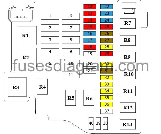
Fuse box diagram engine compartment (USA 2010-2011).
legend.
| Fuse/Relay Location | Fuse Amp Rating | Protected circuits |
|---|---|---|
| F1 | 40A* | Anti-lock brake system (ABS) pump |
| F2 | 50A* | Transmission control module (TCM) |
| F3 | 40A* | Engine cooling fan relay |
| F4 | 40A* | Heater blower relay, Climate controls |
| F5 | 60A* | Passenger compartment fuse panel |
| F6 | 30A* | Body control module (BCM) – door locks |
| F7 | 60A* | Passenger compartment fuse panel |
| F8 | 30A* | Fuel pump |
| F9 | 20A* | ABS module valve |
| F10 | — | Not used |
| F11 | 30A* | Starter inhibit relay, Starter motor |
| F12 | 10A** | Left headlamp (high beam) |
| F13 | 10A** | Right headlamp (high beam) |
| F14 | 10A** | Left headlamp (low beam) |
| F15 | 10A** | Right headlamp (low beam) |
| F16 | 15A** | A/C clutch relay, Mass air flow (MAF) sensor, Powertrain control module (PCM), Fuel injectors, Vehicle speed sensor (VSS), Variable camshaft timing, Canister purge |
| F17 | 15A** | Heated exhaust gas oxygen sensor, Catalyst module sensor |
| F18 | 15A** | Ignition coil |
| F19 | — | Not used |
| F20 | — | Not used |
| F21 | — | Not used |
| F22 | 15A** | BCM – exterior lighting |
| F23 | 7.5A** | Low beam relay |
| F24 | 15A** | BCM – turn signals |
| F25 | 15A** | Low beam relay, Daytime running lights |
| F26 | 7.5A** | Power mirror switch, Driver window switch |
| F27 | 7.5A** | TCM, PCM, Natural vacuum leak detection |
| F28 | — | Not used |
| F29 | 10A** | A/C clutch solenoid and relay |
| F30 | — | Not used |
| F31 | 20A** | Low beam relay |
| F32 | 20A** | BCM – battery saver, horn |
| F33 | 30A** | BCM – rear window defroster |
| F34 | — | Not used |
| F35 | — | Not used |
| F36 | — | Not used |
| F37 | — | Not used |
| F38 | — | Not used |
| F39 | — | Not used |
| F40 | — | Not used |
| R1 | — | Not used |
| R2 | — | Not used |
| R3 | — | Not used |
| R4 | — | High beam relay |
| R5 | — | PCM relay |
| R6 | — | Daytime running lamp |
| R7 | — | Engine cooling fan relay |
| R8 | — | Starter inhibit relay |
| R9 | — | A/C clutch relay |
| R10 | — | Reverse light relay |
| R11 | — | Coil pack relay |
| R12 | — | Low beam relay |
| R13 | — | Heater blower relay |
| *Cartridge fuses **Mini fuses | ||
Fuse box diagram engine compartment (USA 2011-2015).
legend.
| No. | Amps | Circuits protected |
|---|---|---|
| 1 | 60 | as of 2013: Stability assist |
| 40 | Anti-lock brake system | |
| 2 | 40 | as of 2013: Transmission control module |
| 50 | up to 2012: Transmission control module | |
| 3 | 40 | Cooling fan |
| 60 | 1.0L and 1.6L EcoBoost (as of 2013): Cooling fan module | |
| 4 | 40 | Blower motor |
| 5 | 60 | Passenger compartment fuse box supply |
| 6 | 30 | Central locking system |
| 7 | 60 | as of 2013: Ignition switch up to 2012: Passenger compartment fuse panel |
| 8 | 60 | Powertrain control module |
| 9 | 40 | as of 2013: Stability assist module |
| 20 | up to 2012: ABS module valve | |
| 10 | 30 | Engine start Inhibitor |
| 11 | 30 | Electronic fuel pump relay, Fuel tank, Ignition coil |
| 12 | 60 | as of 2013: Power windows |
| 13 | 60 | 1.0L EcoBoost (as of 2013): High-speed cooling fan |
| 14 | – | Not used |
| 15 | – | Not used |
| 16 | – | Not used |
| 17 | 20 | High beam |
| 18 | 15 | as of 2013: Powertrain control module |
| 19 | 20 | as of 2013: Front fog lamps up to 2012: Low beam relay |
| 20 | 15 | Heated exhaust gas oxygen sensor, Catalyst module sensor |
| 21 | 7.5 | as of 2013: High beam up to 2012: Low and High beams coil relay control |
| 22 | 15 | as of 2013: Ignition coll |
| 20 | 1.0L and 1.6L EcoBoost (as of 2013): Ignition coll | |
| 15 | up to 2012: Mass air flow (MAF) sensor, Powertrain control module (PCM), Fuel injectors, Vehicle speed sensor (VSS), Variable camshaft timing, Canister purge | |
| 23 | 15 | as of 2013: Right-hand exterior lamps up to 2012: Daytime running lights |
| 24 | 10 | as of 2013: Emissions system |
| 25 | 15 | as of 2013: Left-hand exterior lamps up to 2012: BCM – exterior lighting |
| 26 | 20 | Horn. Battery back-up sounder. Interior lamps |
| 27 | 7.5 | 1.6L Flex-fuel (as of 2013): Engine cold start system module |
| 15 | 1.0L EcoBoost (as of 2013): Water pump, Active grill shutter | |
| 28 | 15 | Direction Indicators |
| 29 | 20 | as of 2013: Compressed natural gas, fuel control module |
| 30 | 10 | Air conditioning clutch |
| 31 | – | Not used |
| 32 | 7.5 | Powertrain control module. Transmission control unit |
| 33 | 10 | as of 2013: Fuel Injectors |
| 7.5 | 1.0L and 1.6L EcoBoost (as of 2013): Mass air flow sensor | |
| 15 | up to 2012: Ignition coil | |
| 34 | 30 | as of 2013: Heated exterior mirrors up to 2012: BCM – rear window defroster |
| 35 | 10 | as of 2013: Left-hand fog lamp up to 2012: Left headlamp (low beam) |
| 36 | 10 | as of 2013: Right-hand fog lamp up to 2012: Right headlamp (low beam) |
| 37 | 10 | Left-hand high beam |
| 38 | 10 | Right-hand high beam |
| 39 | 2 | up to 2012: Natural vacuum leak detection |
| 40 | – | Not used |
| 41 | – | Not used |
| 42 | – | Not used |
| 43 | – | Not used |
| 44 | – | Not used |
| 45 | – | Not used |
| 46 | – | Not used |
| Relay | ||
| R1 | as of 2013: Compressed natural gas fuel system | |
| R2 | Not used | |
| R3 | Powertrain control module | |
| R4 | Blower motor | |
| R5 | Cooling fan | |
| R6 | Air conditioning clutch | |
| R7 | 1.0L and 1.6L EcoBoost (as of 2013): High-speed cooling fan | |
| R8 | up to 2012: Daytime running lamp | |
| R9 | Engine start Inhibitor | |
| R10 | High beam | |
| R11 | as of 2013: Front fog lamps up to 2012: Low beam relay | |
| R12 | Reversing lamp | |
| R13 | Fuel pump | |
Fuse box diagram engine compartment (USA 2015-2017).
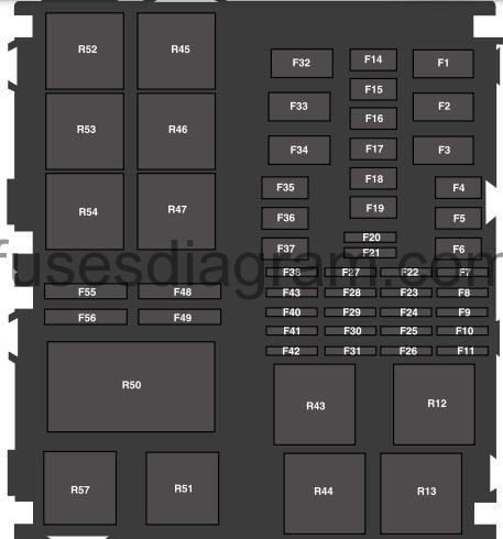
legend.
| No. | Amps | Circuits protected |
|---|---|---|
| F1 | 40 | Anti-lock brake system module |
| 60 | Stability assist | |
| F2 | 40 | Cooling fan relay |
| 60 | 1.6L Ecoboost:High-speed cooling fan relay | |
| F3 | 60 | Passenger compartment fuse box |
| F4 | 20 | Body control module Power door locks |
| F5 | – | Not used |
| F6 | 40 | Blower motor relay Blower motor |
| F7 | – | Not used |
| F8 | – | Not used |
| F9 | 7.5 | Front fog lamp relay Headlamp high beam relay |
| F10 | 15 | Body control module Right-hand exterior lamps |
| F11 | 15 | Body control module Left-hand exterior lamps |
| F14 | – | Not used |
| F15 | – | Not used |
| F16 | – | Not used |
| F17 | – | Not used |
| F18 | – | Not used |
| F19 | 30 | Fuel Injectors |
| F20 | – | Not used |
| F21 | 7.5 | 1.0L and 1.6L EcoBoost: Mass air flow sensor |
| 10 | Fuel Injectors | |
| F22 | 15 | Powertrain control module |
| F23 | 15 | Camshaft position sensor Heated oxygen sensor |
| F24 | 15 | 1.6L Sigma:Ignition coll |
| 20 | 1.0L and 1.6L EcoBoost: Ignition coll | |
| F25 | 10 | Variable camshaft timing Evaporative emission canister purge valve. R57, R45 and R50 relay coll |
| F26 | 7.5 | 1.6L Flex-fuel:ECSS system |
| 15 | 1.0L EcoBoost: Active grille shutter Water pump Air conditioning control module | |
| F27 | – | Not used |
| F28 | – | Not used |
| F29 | – | Not used |
| F30 | – | Not used |
| F31 | – | Not used |
| F32 | 60 | Passenger compartment fuse box |
| F33 | 60 | Power windows |
| F34 | 40 | 6-Speed PowerShift Transmission: Transmission control module |
| 60 | 1.0L EcoBoost: High speed cooling fan | |
| F35 | 40 | Anti-lock brake system with electronic stability control |
| F36 | 30 | Engine start Inhibitor Starter motor solenoid |
| F37 | 30 | Heated rear window Heated exterior mirrors |
| F38 | 20 | Body control module Battery saver |
| F39 | 15 | Body control module Direction Indicators |
| F40 | – | Not used |
| F41 | 10 | Air conditioning clutch |
| F42 | 7.5 | Powertrain control module Transmission control module Evaporative emission canister purge valve |
| F48 | 10 | Left-hand front fog lamp |
| F49 | 10 | Right-hand front fog lamp |
| F55 | 10 | Left-hand high beam |
| F56 | 10 | Right-hand high beam |
| Relay | ||
| R12 | Powertrain control module relay | |
| R13 | Headlamp high beam relay | |
| R43 | Not used | |
| R44 | Front fog lamp relay | |
| R45 | A/C clutch relay | |
| R46 | Not used | |
| R47 | Fuel pump relay | |
| R50 | 1.0L and 1.6L EcoBoost: High speed cooling fan | |
| R51 | Start Inhibit relay | |
| R52 | Blower motor relay | |
| R53 | Not used | |
| R54 | Reversing lamp | |
| R57 | Cooling fan relay | |
Main fuse box in engine compartment.
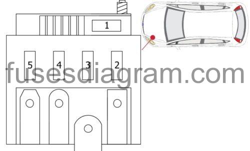
legend.
| Fuses | Amps | Circuits Protected |
|---|---|---|
| 1 | 450A | Starter |
| 2 | 60A | Electronic power steering |
| 3 | 200A | Fuse and relay box in engine compartment |
| 4 | 70A | PTC heater or Additional heater |
| 5 | 50A | PTC heater |