For the Honda Stream 2001, 2002, 2003, 2004, 2005, 2006 model year.
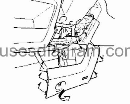
Fuse box in passenger compartment.
fuse box location.
fuse box diagram.
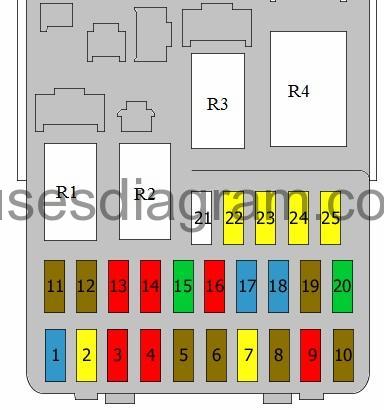
legend.
| Fuse | Amps | Circuits protected |
|---|---|---|
| 1 | 15A | Ignition coil(s) |
| 2 | 20A | Heated seats |
| 3 | 10A | Daylight running system relay Or Front fog lights (20A also used) |
| 4 | 10A | Alternator Cruise control unit Camshaft position sensor Detector, electrical load Inlet valve timing control solenoid Evaporative purge control solenoid Primary heated oxygen sensor Secondary heated oxygen sensor Vehicle speed sensor |
| 5 | 7,5A | Multiplex control unit |
| 6 | 7,5A | Headlight levelling control unit Headlight levelling switch Windows Power window relay Sunroof open relay Sunroof close relay |
| 7 | 20A | Sunroof |
| 8 | 7,5A | Optional connector Multiplex control unit Audio unit Keyless entry control unit Automatic transmission shift interlock |
| 9 | 10A | Rear wiper and washer Intermittent rear wiper |
| 10 | 7,5A | Multiplex control unit Automatic transmission control relay Reversing lights Direction indicators Keyless entry control unit Third brake light Security control unit |
| 11 | 7,5A | ABS modulator unit |
| 12 | 7,5A | Multiplex control unit |
| 13 | 10A | SRS module |
| 14 | 10A | Optional connector Heated electric mirrors Climate control unit Heater control panel Recirculation control motor Blower relay Condenser fan relay Cooling fan relay Heated rear windscreen relay |
| 15 | 30A | Headlight washer |
| 16 | 10A | Rear blower |
| 17 | 15A | Engine control unit Inertia switch Fuel pump SRS module |
| 18 | 15A | Cigarette lighter |
| 19 | 7,5A | Hazard warning light relay |
| 20 | 30A | Windscreen washer(s) Windscreen wiper(s) Multiplex control unit |
| 21 | not used | |
| 22 | 20A | Front right window |
| 23 | 20A | Front left window |
| 24 | 20A | Rear left power window |
| 25 | 20A | Rear right power window |
| R1 | Starter relay | |
| R2 | Tail light(s) relay | |
| R3 | Window relay | |
| R4 | Hazard warning light relay Direction indicator relay |
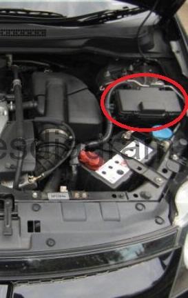
Fuse box in engine compartment.
fuse box location.
fuse box layout.
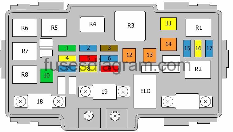
legend.
| Fuse | Amps | Circuits protected |
|---|---|---|
| 1 | 30A | Condenser fan Optional connector Air-conditioning compressor clutch |
| 2 | 15A | Front parking lights Tail light(s) Number plate light(s) Tail light relay Dashboard illumination Multiplex control unit Fog lights |
| 3 | 7,5A | Interior light(s) Ignition key light Tail lights |
| 4 | 20A | Blower motor |
| 5 | 10A | Hazard warning light relay Security control unit |
| 6 | 15A | Crankshaft position sensor Control unit Fuel injectors IAC valve Immobiliser control unit TDC sensor |
| 7 | 15A | ABS modulator unit Brake lights Engine control unit Horn Alarm horn |
| 8 | 20A | ABS modulator unit |
| 9 | 10A | Data link connector Multiplex control unit Immobiliser control unit Audio Keyless entry control unit Security control unit Gauge wiring loom |
| 10 | 30A | ABS modulator unit |
| 11 | 20A | Heated rear windscreen |
| 12 | 40A | Blower motor |
| 13 | 40A | Fuse box in passenger compartment, fuses 7, 22 – 25 |
| 14 | 40A | Fuse box in passenger compartment, fuses 2, 3, 5, 15, 16 |
| 15 | 15A | Left headlight Dashboard light, main beam |
| 16 | 20A | Multiplex control unit |
| 17 | 15A | Right headlight |
| 18 | Not used | |
| 19 | 100A | Battery Power distribution |
| 20 | 50A | Ignition switch, BAT |
| R1 | Headlight relay, right side | |
| R2 | Headlight relay, left side | |
| R3 | Blower relay | |
| R4 | Heated rear windscreen relay | |
| R5 | Condenser fan relay | |
| R6 | Air-conditioning compressor clutch relay | |
| R7 | Horn relay | |
| R8 | Not used | |
| ELD | Detector, electrical load |