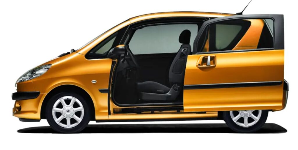
For Peugeot 1007 – 2005, 2006, 2007, 2008, 2009, 2010, 2011 year of release. Engine displacement 1.4, 1.6, liters. You will also know where the fuses are located, including the fuel pump fuse (fuel pump), cigarette lighter fuses, cooling fan, entry, low beam, parking lights, reverse, electric windows, etc.
| The cigarette lighter fuse is located under number F22/20A – fuse box diagram in the block (option 1). The cigarette lighter fuse is located under number F9/30A – fuse box diagram in the block (option 2). |
Content:
Location of electronic components.
Fuse box in the passenger compartment.
Fuse box in engine compartment.
Fuse box №2 in the engine compartment.
Location of electronic components.
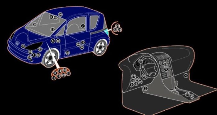
| 1 | ABS control module-engine bay, RH front |
| 2 | AC blower speed resistor – under fascia |
| 3 | AC control module |
| 4 | Alarm system control module |
| 5 | Alarm system siren- LH rear engine compartment |
| 6 | Light sensor |
| 7 | Audio unit output amplifier-RH load area |
| 8 | Battery |
| 9 | Data link connector (DLC) |
| 10 | Door mirror retract relay-behind fascia fuse box/relay plate 1 |
| 11 | Electric window control module – indoor |
| 12 | Electric window control module – indoor |
| 13 | Electronic stability program (ESP) control module – in ABS control module |
| 14 | Engine control module (ECM) – near battery |
| 15 | Engine coolant blower motor control module-fan cowling |
| 16 | Fuse box/relay plate, engine bay 1 |
| 17 | Fuse box/relay plate, engine bay 2-attached to engine bay fuse box/relay plate 1 |
| 18 | Fuse box/relay plate, engine bay 3 – near engine bay fuse box/relay plate 1 |
| 19 | Fuse box/relay plate, fascia 1 |
| 20 | Fuse box/relay plate, fascia 2-attached to fascia fuse box/relay plate 1 |
| 21 | Fuse box/relay plate, load area |
| 22 | Glow plug control module |
| 23 | Heater blower speed resistor- behind fascia |
| 24 | Horn |
| 25 | Instrumentation control module |
| 26 | Multifunction control module1- in corporated in fascia fuse box/relayplate1-functions: Air conditioning (AC), audio unit, cigarette lighter, digital multifunction display, electric windows, hazard warning lamps, heated rear window, indicators, interior lamps, rear fog lamp, rear screen wiper, seat belt audible warning control module, seat heaters, side/taillamps, sliding door control module, stop lamps, sunroof |
| 27 | Multifunction control module1- in corporated in fascia fuse box/relayplate1-functions: Air conditioning (AC), audio unit, cigarette lighter, digital multifunction display, electric windows, hazard warning lamps, heated rear window, indicators, interior lamps, rear fog lamp, rear screen wiper, seat belt audible warning control module, seat heaters, side/taillamps, sliding door control module, stop lamps, sunroof |
| 28 | Multifunction control module 3-incorporated in engine bay fuse box/relay plate 1-functions: Engine coolant blower motor relays, engine bay fuse box/relay plate 3, exhaust gas recirculation (EGR), fuel rail pressure (FRP) control valve, glow plug control module, high-pressure fuel pump, ignition coils, injectors, starter motor |
| 29 | Outside air temperature sensor-in RH door mirror |
| 30 | Parking aid control module- under RH seat |
| 31 | Power steering control module- near battery |
| 32 | Satellite fuse- LH load area |
| 33 | Seat belt audible warning control module-under driver’s seat |
| 34 | Sliding door control module- under LH seat |
| 35 | Steering column function control module |
| 36 | Sun roof control module |
| 37 | Supplementary restraint system (SRS) control module |
| 38 | Trailer control module |
| 39 | Transmission control module (TCM) – engine bay, RH front |
| 40 | Tyre pressure monitor control module – under LH seat |
| 41 | Windscreen wiper rain sensor |
| 42 | Yawrate sensor |
Fuse box in the passenger compartment.
LHD:
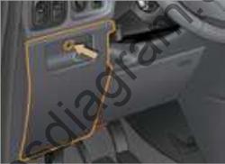
Turn the screw a quarter turn, then tilt the cover to open it.
Turn the lever a quarter turn, then push and tilt the housing to access the fuses.
RHD:
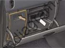
Open the glove box, then tilt the lid to open it.
Turn the lever a quarter turn, then push and tilt the housing to access the fuses.
fuse layout diagram in the block (option 1).
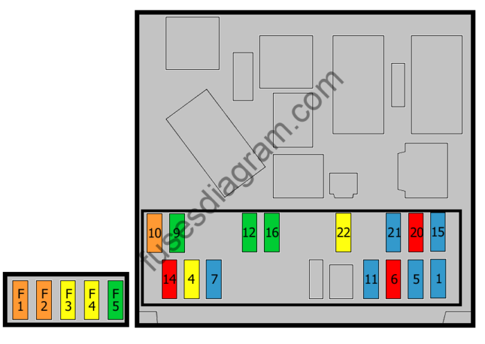
Fuse assignment.
| № | Amp | Circuits Protected |
|---|---|---|
| 1 | 15A | Diagnostic connector power supply Electric door(s) Steering wheel controls |
| 4 | 20A | Clock Multifunction display Radio accessory Telephone Alarm control unit |
| 5 | 15A | Alarm siren |
| 6 | 10A | Diagnostic socket Steering wheel rotation sensor Seat belt control unit |
| 7 | 15A | Alarm control unit Rain detector |
| 9 | 30A | Towing ball |
| 10 | 40A | Heated rear window Heated mirror |
| eleven | 15A | Back windshield wiper |
| 12 | 30A | Electric windows Sunroof |
| 14 | 10A | Fuse box No. 1 in engine compartment Steering wheel controls Airbags Seat belt pretensioners |
| 15 | 15A | Dashboard Multifunction display Audio system Telephone CD changer Air conditioning system Parking assistance Electric door(s) |
| 16 | 30A | Central locking |
| 20 | 10A | Stop light, right |
| 21 | 15A | Stop light, left Additional stop light |
| 22 | 20A | Welcome lamp(s) Reading light(s) Glove box warning light Cigarette lighter Electric mirror(s) |
| F1 | 40A | Electric door(s) |
| F2 | 40A | Electric door(s) |
| F3 | 20A | Heated seats) |
| F4 | 20A | Audio amplifier |
| F5 | 30A | Not used |
fuse layout diagram in the block (option 2).
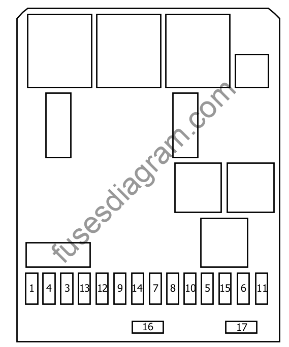
Fuse assignment.
| F1 | (15A) Rear wiper motor |
| F3 | (5A) Supplemental Restraint System (SRS) Control Module |
| F4 | (10A) Data Link Connector (DLC), Fuel Additive Pump, Clutch Pedal Position Switch (CPP), Steering Column Function Control Module |
| F5 | (30A) Sunroof, electric windows-front |
| F6 | – |
| F7 | (5A) Interior lighting, glove box lighting |
| F8 | (20A) Alarm system, exterior mirror retraction relay, steering column function control module, type pressure monitor control module, multifunction display, audio unit, telephone transceiver, power control module trailer |
| F9 | (30A) Audio unit, cigarette lighter |
| F10 | (15A) Alarm system siren |
| F11 | (15A) Data Link Connector (DLC), Ignition Switch, Sliding Door Contact Plate, Left, Sliding Door Contact Plate, Right |
| F12 | (15A) Supplemental Restraint System (SRS) Control Module, Windshield Wiper Rain Sensor, Ambient Light Sensor, Cargo Area Fuse Box/Relay Plate, Trailer Control Module |
| F13 | (5A) Engine Compartment Fuse Box/Relay Plate1, ABS, Brake Pedal Position Switch (BPP), Transmission Gear Selector Switch, Vehicle Speed Sensor (VSS) |
| F14 | (15A) Instrument panel, parking assist control module, telephone system, climate control module, seat belt light, headlight adjustment switch, sliding door control switch, sliding door control module , audio unit output amplifier |
| F15 | (30A) Centralized locking |
| F 16 | Fuse lien |
| F17 | (40A) Exterior mirrors, heated rear window |
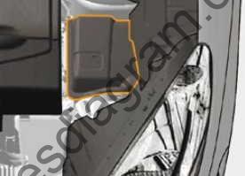
Fuse box in engine compartment.
Unclip the cover to access the fuses.
fuse layout diagram in the block (option 1).
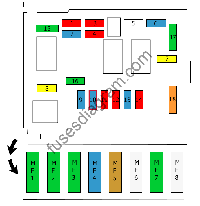
Fuse assignment.
| № | Amp | Circuits Protected |
|---|---|---|
| 1 | 10A | Reversing light(s) Transmission control unit |
| 2 | 15A | Fuel pump |
| 3 | 10A | ABS control unit ESP control unit |
| 4 | 10A | Clutch switch Stop light switch |
| 5 | Not used | |
| 6 | 15A | Front fog light(s) |
| 7 | 20A | Headlight washer pump |
| 8 | 20A | Fan relay Injection control unit |
| 9 | 15A | Light beam managed by the left dimmer |
| 10 | 15A | Light beam managed by the right dimmer |
| eleven | 10A | Left main beam |
| 12 | 10A | Right main beam |
| 13 | 15A | Warning |
| 14 | 10A | Wash pumps, front and rear |
| 15 | 30A | Ignition coil Solenoid(s) Canister purge solenoid Lambda probe(s) Injectors |
| 16 | 30A | Air Pump Relay Diesel Fuel Heater |
| 17 | 30A | Wiper |
| 18 | 40A | Fan |
| MF1 | 30A | Cooling fan |
| MF2 | 30A | ABS control unit ESP control unit |
| MF3 | 30A | ABS control unit ESP control unit |
| MF4 | 60A | BSI (Intelligent utility box) |
| MF5 | 70A | BSI (Intelligent utility box) |
| MF6 | 80A | Electric door(s) Audio amplifier Heated seats |
| MF7 | 30A | Ignition switch |
| MF8 | 80A | Power steering |
fuse layout diagram in the block (option 2).
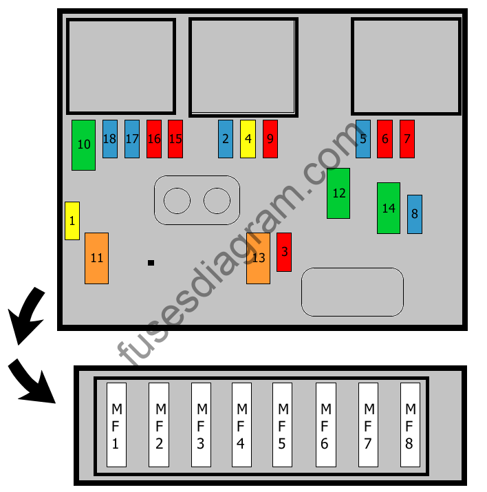
| F1 | (20A) Engine control module (ECM), engine coolant blower motor, mass air flow (MAF) sensor, fuel pump (FP) |
| F2 | (15A) Horn |
| F3 | (10A) Windscreen washer pump, rear screen washer pump |
| F4 | (20A) Headlamp washer pump |
| F5 | (15A) Fuel pump (FP) |
| F6 | (10A) Power steering, fuel/water separator sensor |
| F7 | (10A) Engine bay fuse box/relay plate 3 |
| F8 | (20A) Starter motor |
| F9 | (10A) ABS system, electronic stability program (ESP) control module, brake pedal position (BPP) switch |
| F10 | (30A) Engine control module (ECM), ignition coil, injectors, heated oxygen sensor (HO2S) 1/2, evaporative emission (EVAP) canister purge valve, fuel pump (FP), fuel rail pressure (FRP) control valve, mass air flow (MAF)sensor, turbocharger (TC) boost pressure control valve |
| F11 | (40A) AC/heater blower control module |
| F12 | (30A) Windscreen wiper motor |
| F13 | (40A) Fuse box/relay plate, fascia1 |
| F14 | (30A) Fuel heater (Diesel) |
| F15 | (10A) Headlamp, right |
| F16 | (10A) Headlamp, left |
| F17 | (15A) Headlamp, left |
| F18 | (15A) Headlamp, right |
| MF1 | (70A) Engine coolant blower motor control module |
| MF2 | (30A) ABS system, electronic stability program (ESP) |
| MF3 | (30A) ABS system, electronic stability program (ESP) |
| MF4 | (60A) Fuse box/relay plate, fascia1 |
| MF5 | (60A) Fuse box/relay plate, fascia1 |
| MF6 | (30A) Transmission |
| MF7 | (80A) Fuse box/relay plate, fascia2, sliding door control module |
| MF8 | (80A) Power steering |
Fuse box №2 in the engine compartment.
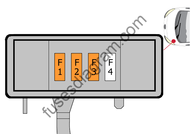
Fuse F1
Air conditioner fan
40.0 A
Fuse F2
Air conditioner fan
40.0 A
Fuse F3
Air Conditioner Fan
40.0 A
F4 fuse
Not used

