For the Volkswagen Golf 6 2008, 2009, 2010, 2011, 2012, 2013 model year.
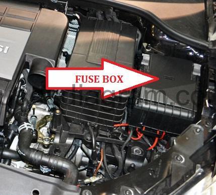
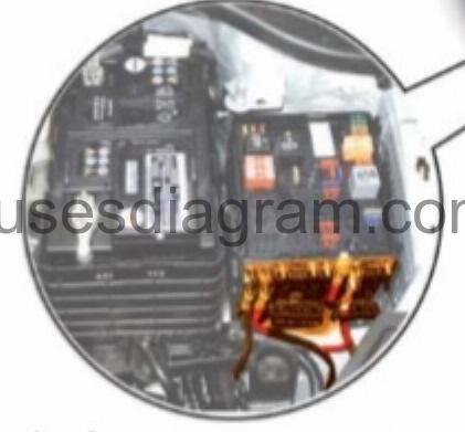
Fuse box location.

Fuse box on left in engine compartment Golf 6.
fuse box diagram type 1.
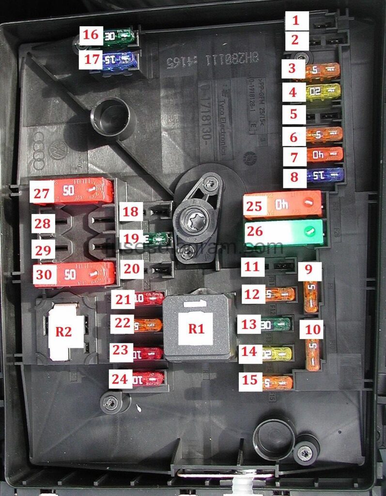
legend.
R1 |
|
R2 | Petrol: Secondary air injection (AIR) pump relay |
F1 | – |
F2 | (5A) |
F3 | (5A) |
F4 | (30A) ABS control module |
F5 | (15A) |
F6 | (5A) |
F7 | (15A) Ignition main circuits |
F8 | (15A) Multifunction display control module |
F9 | (5A) Telematics |
F10 | (5A/10A) |
F11 | (20A) Engine coolant blower motor |
F12 | (5A) CAN data bus gateway control module |
F13 | (15A) Engine control module (ECM) |
F14 | (20A) Engine management system |
F15 | (5A/10A) Engine management system |
F16 | (30A) |
F17 | (15A) Horn |
F18 | (30A) Audio system |
F19 | (30A) Windscreen wiper control module |
F20 | (40A) Engine management system |
F21 | (15A/25A) Enginemanagement system |
F22 | (5A) Clutch pedal position (CPP) sensor |
F23 | (5A/10A/15A) Engine management system |
F24 | (10A) Engine management system |
F25 | (40A) ABS control module |
F26 | (40A) |
F27 | (40A/50A) |
F28 | – |
F29 | (50A) Electric seats |
F30 | (50A) Ignition switch circuits |
Legend (pre 05.2009).
R1 | Engine control (EC) relay |
R2 | Petrol: Secondary air injection (AIR) pump relay |
FI | (30A) Windscreen wiper motor |
F2 | (30A) Transmission control module (TCM) |
F3 | (5A) Multifunction control module |
F4 | (20A) ABS control module |
F5 | (15A) Transmission control module (TCM) |
F6 | (5A) instrumentation control module |
F7 | (40A) Ignition main circuits |
F8 | (15A/25A) |
F9 | (5A) Telematics |
fio | (5A/10A) Engine control module(ECM) |
fii | (20A) Auxiliary heater |
F12 | (5A) CAN data bus gateway control module |
F13 | (15A/30A) Engine control module(ECM) |
F14 | (20A) Engine management system |
F15 | (5A/10A) Engine management system |
F16 | (30A) Exterior lamps |
F17 | (15A) Horn |
F18 | (30A) Audio system |
F19 | (30A) Windscreen wiper motor |
F20 | (10A) Engine coolant pump motor |
F21 | (10A/15A/20A) |
F22 | (5A) |
F23 | (5A/10A/15A) engine management system |
F24 | (10A) engine management system |
F25 | (40A) ABS control module |
F26 | (30A) Exterior lamps |
F27 | (40A/50A) |
F28 | (30A/40A) Ignition main circuits |
F29 | (50A) |
F30 | (50a) Ignition switch circuits |
Legend (05.2009-11.2009).
1 | Engine control (EC) relay |
2 | Petrol: Secondary air injection (AIR) pump relay |
F1 | (30A) Windscreen wiper motor |
F2 | (30A) Transmission control module (TCM) |
F3 | (20A) Multifunction control module |
F4 | (20A) ABS control module |
F5 | (15A) Transmission control module (TCM) |
F6 | (5A) |
F7 | (40A) Ignition main circuits |
F8 | (15A/25A) |
F9 | (5A) Telematics |
F10 | (5A/10A) Engine control module(ECM) |
F11 | (20A) Auxiliary heater |
F12 | (5A) CAN data bus gateway control module |
F13 | (15A/30A) Engine control module(ECM) |
F14 | (20A) engine management system |
F15 | (5A/10A) engine management system |
F16 | (30A) |
F17 | (15A) Horn |
F18 | (30A) Audio system |
F19 | (30A) Windscreen wiper motor |
F20 | (10A/20A) |
F21 | (10A/15A/20A) |
F22 | (5A) |
F23 | (5A/15A) engine management system |
F24 | (10A) engine management system |
F25 | (40A) ABS control module |
F26 | (30A) |
F27 | (40A/50A) |
F28 | (30A) Ignition main circuits |
F29 | (50A) |
F30 | (50A) Ignition switch circuits |
Legend (since 11.2009).
R1 | Engine control (EC)relay |
R2 | Petrol: Secondary air injection (AIR) pump relay |
F1 | – |
F2 | (30A) |
F3 | (20A) Multifunction control module |
F4 | (30A) ABS control module |
F5 | (15A) Transmission control module (TCM) |
F6 | (5A) |
F7 | (40A) Ignition main circuits |
F8 | (15A/25A) |
F9 | (5A) Telematics |
F10 | (5A/10A) Engine control module(ECM) |
F11 | (20A) Auxiliary heater |
F12 | (5A) CAN data bus gateway control module |
F13 | (15A/30A) Engine control module(ECM) |
F14 | (20A) engine management system |
F15 | (5A/10A) engine management system |
F16 | (30A) |
F17 | (15A) Horn |
F18 | (30A) Audio system |
F19 | (30A) Windscreen wiper motor |
F20 | (10A/20A) |
F21 | (10A/15A/20A) |
F22 | (5A) Clutch pedal position (CPP) sensor |
F23 | (5A/10A/15A) |
F24 | (10A) engine management system |
F25 | (40A) ABS control module |
F26 | (30A) |
F27 | (40A/50A) |
F28 | – |
F29 | (50A) |
F30 | (50A) Ignition switch circuits |
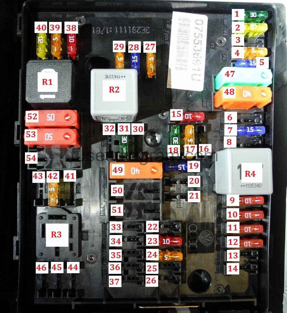
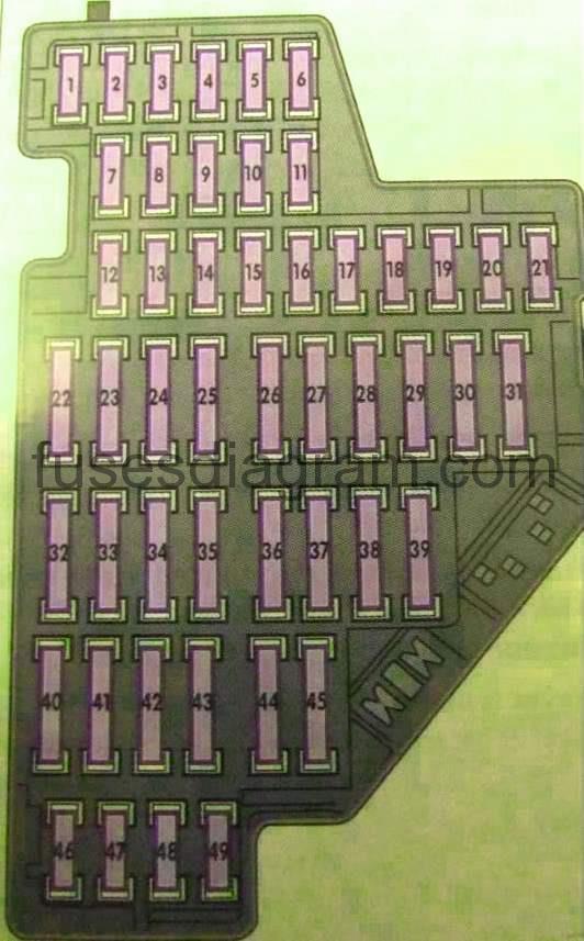
Fuse box diagram (type 2).
R1 |
|
R2 | Engine coolant pump relay |
R3 | – |
R4 |
|
F1 | (30A) Multifunction control module |
F2 | (20A) ABS control module |
F3 | – |
F4 | (5A) Multifunction control module |
F5 | (15A) Horn |
F6 | – |
F7 | (15A) engine management system |
F8 | – |
F9 | (10A) engine management system |
F10 | (10A) engine management system |
F11 | (10A) engine management system |
F12 | (10A) engine management system |
F13 | (15A) Transmission control module (TCM) |
F14 | – |
F15 | (10A) Engine coolant pump motor |
F16 | – |
F17 | (5A) |
F18 | (30A) Audio system |
F19 | (15A) |
F20 | (5A) Auxiliary heater |
F21 | – |
F22 | – |
F23 | (10A) |
F24 | (5A) CAN data bus gateway control module |
F25 | – |
F26 | – |
F27 | (5A) Exhaust gas control solenoid |
F28 | (15A) Engine control module(ECM) |
F29 | (5A) Engine coolant pump motor |
F30 | – |
F31 | (30A) Windscreen wiper motor |
F32 | – |
F33 | – |
F34 | – |
F35 | – |
F36 | – |
F37 | – |
F38 | (10A) engine management system |
F39 | (5A) Clutch pedal position (CPP) sensor |
F40 | (20A) engine management system |
F41 | – |
F42 | (5A) engine management |
F43 | – |
F44 | – |
F45 | – |
F46 | – |
F47 | (30A) Multifunction control module |
F48 | (40A) ABS control module |
F49 | (40A) Ignition main circuits |
F50 | – |
F51 | – |
F52 | (50A) Ignition switch circuits |
F53 | (50A) |
F54 | – |
Multi fuse back-up fuse box Volkswagen Golf 6.
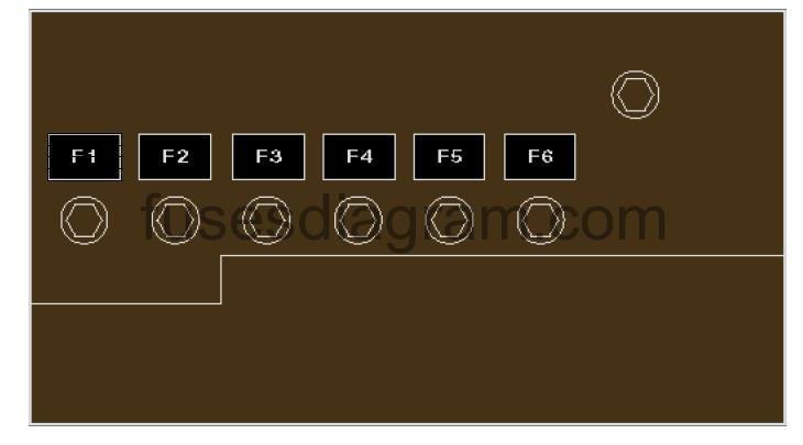
fuse box diagram type 1.
F1 | (200A) Altemator |
F2 | (80A) Power steering control module |
F3 | (50A) Engine coolant blower motor |
F4 | (80A) Engine coolant heater |
F5 | (80A) |
F6 | (40A) Engine coolant heater |
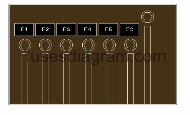
fuse box diagram type 2.
F1 | (150A/200A) Alternator |
F2 | (80A) Power steering control module |
F3 | (50A) Engine coolant blower motor control module |
F4 | (30A) CHGA engine: Gas fuel control module |
F5 | (80A) |
F6 | (40A) Auxiliary heater |
fuse box diagram type 3.
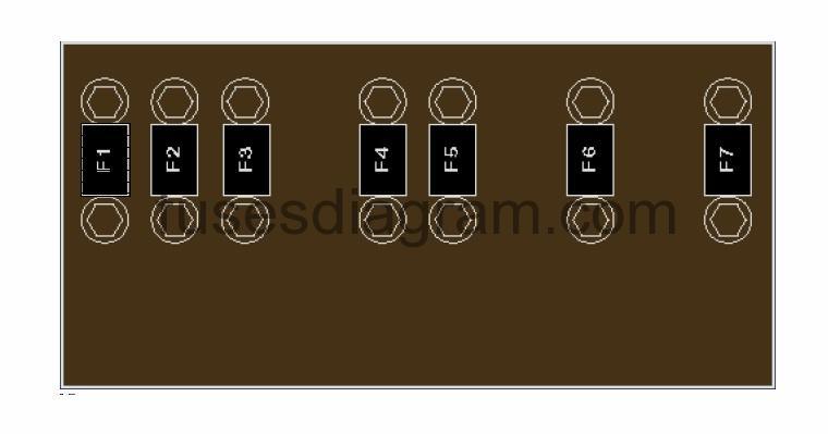
F1 | (150A/200A) Alternator |
F2 | (80A) Power steering control module |
F3 | (50A) Engine coolant blower motor control module |
F4 | – |
F5 | (80A) |
F6 | – |
F7 | – |
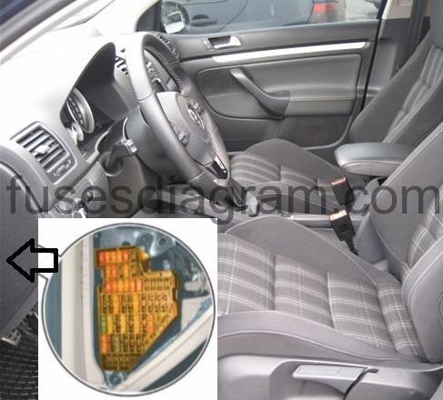
Fuse box in passenger compartment Volkswagen Golf 6.
Fuse box locaion.
On left of dash panel.
fuse box diagram.
left hand drive
right hand drive
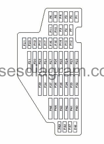
F1 | (10A) Headlight range control |
F2 | (10A) Electrical socket for trailer, ABS, ESP, Combi instrument, brake light switch |
F3 | (5A) Supplementary restraint system (SRS) control module |
F4 | (5A) ABS, ESP |
F5 | (10A) Headlamp level control module |
F6 | (10A) Headlamp level control module |
F7 | – |
F8 | – |
F9 | – |
F10 | – |
F11 | – |
F12 | (10A) Central locking for front doors |
F13 | (10A) Rain sensor |
F14 | (10A) Selector mechanism for the automatic gearbox |
F15 | (20A) Central locking for rear doors |
F16 | (10A) |
F17 | (10A/5A) Interior monitoring/anti-tow alarm |
F18 | – |
F19 | (5A) Special vehicle equipment |
F20 | – |
F21 | (10A) Steering column lock control module |
F22 | (40A) AC/heater blower motor control module |
F23 | (30A) Front electric windows |
F24 | (20A) Multifunction control module |
F25 | (25A) Heated rear window |
F26 | (30A) Rear electric windows |
F27 | (15A) Fuel pump(FP) |
F28 | (15A) Audio system |
F29 | – |
F30 | (20A) Transmission control module (TCM) |
F31 | (20A) Brake servo vacuum pump |
F32 | (30A) Auxiliary power sockets |
F33 | (25A) Sunroof control module |
F34 | (15A) Electric seats |
F35 | (10A) Suspension control module |
F36 | (20A) Head lamp washers |
F37 | (30A) Heated seats |
F38 | – |
F39 | – |
F40 | (40A) AC/heater blower motor control module |
F41 | (15A) Rear screen wiper motor |
F42 | (20A) Auxiliary power sockets, cigarette lighter |
F43 | (15A) Trailer control module |
F44 | (20A) Trailer control module |
F45 | (15A) Trailer control module |
F46 | – |
F47 | (5A) Instrument panel |
F48 | (10A) |
F49 | – |
Relay carrrer above onboard supply control unit.
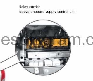
relay diagram type 1.
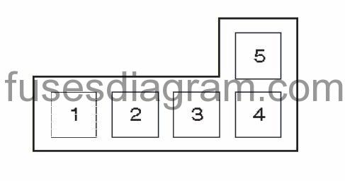
1 | Ignition main circuits relay |
2 | Ignition auxiliary circuits relay |
3 |
|
4 | Heated rear window relay |
5 | Starter motor relay |
relay diagram type 2.
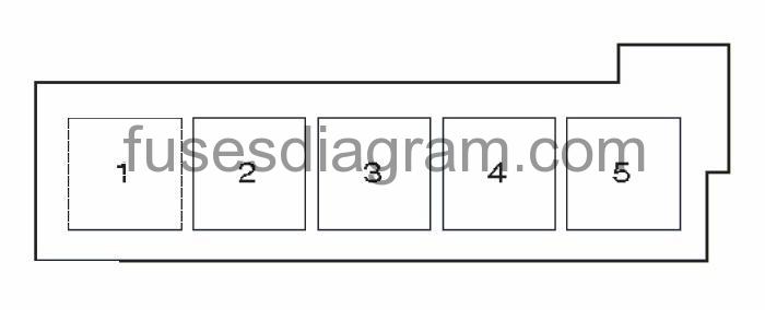
1 | Ignition main circuits relay |
2 | Ignition auxiliary circuits relay |
3 | Horn relay |
4 | Heated rear window relay |
5 | Starter motor relay |