For the Volkswagen Amarok 2011, 2012, 2013, 2014, 2015, 2016, 2017 model year.
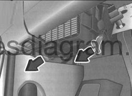
Fuse box in passenger compartment.
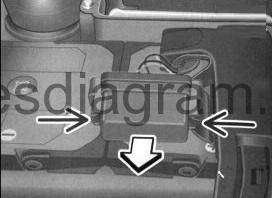
Fuse box is located under driver’s side of instrument panel.
fuse box diagram (05/2011-) with start and stop system).
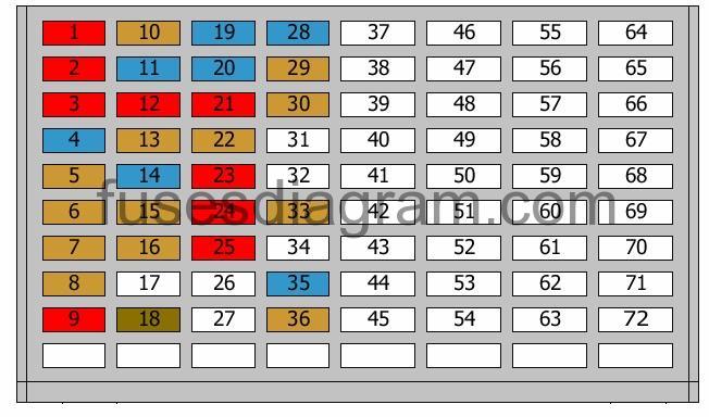
legend.
| Fuse | AMPS | Circuits Protected |
|---|---|---|
| 1 | 10A | ABS control unit TCS/ESP button Switch module for driving mode |
| 2 | 10A | Steering column control(s) |
| 3 | 10A | Reversing light switch Parking assistance control unit |
| 4 | 15A | Power supply control unit |
| 5 | 5A | Mass airflow meter |
| 6 | 5A | Trailer detection control unit |
| 7 | 5A | Multimedia display |
| 8 | 5A | Ignition lock |
| 9 | 10A | Airbag control unit Passenger’s side airbag deactivation light |
| 10 | 5A | Engine control unit |
| 11 | 15A | Differential control unit |
| 12 | 10A | Fuel pressure control solenoid Fuel metering solenoid |
| 13 | 5A | Exhaust flap valve Exhaust gas cooler solenoid Turbo pressure control solenoid |
| 14 | 15A | Coolant circulation pump |
| 15 | 5A | Terminal 30 voltage supply relay Coolant circulation pump (additional coolant heater) |
| 16 | 5A | Voltage regulator(s) Data bus diagnostic interface |
| 17 | Not used | |
| 18 | 7.5A | Washer pump |
| 19 | 15A | Power supply control unit |
| 20 | 15A | Power supply control unit |
| 21 | 10A | Power supply control unit |
| 22 | 5A | Vehicle position recognition control unit |
| 23 | 10A | Engine control unit |
| 24 | 10A | Alarm horn |
| 25 | 10A | Crankcase heater |
| 26 | Not used | |
| 27 | Not used | |
| 28 | 15A | Power supply control unit |
| 29 | 5A | Light switch |
| 30 | 5A | Starter relay 1 Starter relay 2 |
| 31 | Not used | |
| 32 | Not used | |
| 33 | 5A | Mirror switch |
| 34 | Not used | |
| 35 | 15A | Oxygen sensor in front of the catalytic converter |
| 36 | 5A | Fuel pump relay Terminal 30 voltage supply relay Engine control unit |
| 37 | Not used | |
| 38 | 15A | 12V socket |
| 39 | 25A | Trailer detection control unit |
| 40 | 25A | Trailer detection control unit |
| 41 | 25A | Trailer detection control unit |
| 42 | 15A | Diagnostic connector Control unit with display in the dash panel insert Steering column control(s) Air-conditioning high-pressure sensor Air quality sensor Differential control unit Transfer box control unit Vehicle position recognition control unit High-level brake light Brake light switch Oil level and temperature sensor Fuse box in passenger compartment, fuse 16 Transfer box control unit warning lights |
| 43 | 25A | Power supply control unit |
| 44 | 30A | Power supply control unit |
| 45 | 15A | Diagnostic connector Control unit with display in the dash panel insert Steering column control(s) Air-conditioning control unit Climatronic control unit Heater switch |
| 46 | 25A | Transfer box control unit |
| 47 | 20A | Power supply control unit |
| 48 | 20A | Driver’s door control unit |
| 49 | 20A | Front passenger’s door control unit |
| 50 | 20A | Door control unit, rear left |
| 51 | 20A | Door control unit, rear right |
| 52 | 15A | Power socket |
| 53 | 25A | Power supply control unit |
| 54 | 15A | Cigarette lighter |
| 55 | 25A | Power supply control unit |
| 56 | Not used | |
| 57 | 30A | Heated seat switches Heated seat control unit |
| 58 | Not used | |
| 59 | 20A | Additional 12V socket |
| 60 | 5A | Trailer detection control unit Power supply control unit |
| 61 | 5A | Trailer detection control unit Power supply control unit |
| 62 | 20A | Additional heater control unit Coolant circulation pump (additional coolant heater) |
| 63 | 10A | Illumination |
| 64 | 40A | Heater switch Climatronic control unit Air-conditioning control unit |
| 65 | 15A | Engine control unit |
| 66 | 30A | Power supply control unit |
| 67 | 30A | Voltage regulator(s) Data bus diagnostic interface |
| 68 | 5A | Telephone control unit |
| 69 | 15A | Multimedia display |
| 70 | 5A | Multimedia display |
| 71 | 25A | Multimedia display |
| 72 | 10A | Multimedia display |
Relay box in passenger compartment Volkswagen Amarok.
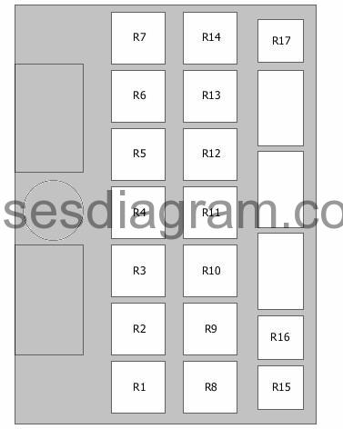
Relay R1 – Relay, additional coolant heater
Relay R2 – Power supply relay
Relay R3 – Fuel pump relay
Terminal 30 voltage supply relay
Relay R4 – Starter motor relay
Relay R5 – Not used
Relay R6 – Not used
Relay R7 – Not used
Relay R8 – Coolant pump relay
Relay R9 – Power supply relay 2
Relay R10 – Terminal 15 voltage supply relay
Relay R11 – Not used
Relay R12 – Not used
Relay R13 – Not used
Relay R14 – Not used
Relay R15 – Power supply relay
Relay R16 – Terminal 58 relay
Relay R17 – Main relay
Fuse box in engine compartment.
location.
fuse box layout.

| Fuse | AMPS | Circuits Protected |
|---|---|---|
| 7 | 40A | ABS control unit |
| 8 | 30A | Fuel pump relay Fuel pressure pump |
| 9 | 30A | ABS control unit |
| 10 | 5A | Power supply control unit Or Battery monitor control unit |
| 11 | Not used | |
| 12 | Not used | |
| FL1 | 175A | Alternator |
| FL2 | 175A | use box in passenger compartment, fuses 4, 8, 11, 15, 19 – 24, 43 – 51, 62 – 64, 66, 67 Or Starter Fuse box in passenger compartment, fuses 1 – 15, 19 – 25, 33 – 38, 42 – 52, 54, 56, 57, 59, 62 – 72 Or Starter Steering column control(s) Fuse box in passenger compartment, fuses 1 – 16, 19 – 25, 28 – 30, 35, 36, 38, 42 – 55, 57, 59, 62 – 72 |
| FL3 | 40A | Multimedia display |
| FL4 | 80A | Radiator fan control unit (110A also used) |
| FL5 | 50A | Glow plug control unit |
| FL6 | 80A | Fuse box in passenger compartment, fuses 39 – 41 |