For the Audi Allroad (4BH) 2001, 2002, 2003, 2004, 2005, 2006 model year.
| Cigarette lighter fuse – (fuse box in passenger compartment, fuse №33/15A) |
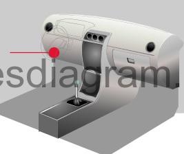
Fuse box in passenger compartment.
fuse box diagram (pre 2002).
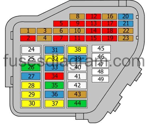
legend ( -2002).
| Fuse | Amps | Circuits protected |
|---|---|---|
| 1 | 5A | Heated washers |
| 2 | 10A | Direction indicators |
| 3 | 5A | Glovebox illumination |
| 4 | 5AA | Number plate light(s) |
| 5 | 10A | Air conditioning Telephone Parking assistance Instrument panel Mirror(s) Navigation system Additional heater Tyre pressure monitor control unit Self-levelling suspension system Automatic gearbox Bulb check control unit |
| 6 | 5A | Central locking |
| 7 | 10A | ABS control unit ESP control unit Cruise control |
| 8 | 5A | Telephone Telematics |
| 9 | 10A | Heated mirror(s) |
| 10 | 5A | Headlight range control |
| 11 | 10A | Automatic anti-dazzle rear-view mirror |
| 12 | 10A | On-board diagnostic Terminal 30 voltage supply |
| 13 | 10A | Brake light(s) |
| 14 | 10A | Interior light(s) Central locking Seat adjustment memory |
| 15 | 10A | Instrument panel Additional heater Navigation system Seat and mirror memory Solar cell isolation relay |
| 16 | 5A | Steering angle sensor (ESP) |
| 17 | 10A | Levelling system Radio Navigation system Tyre pressure monitor control unit Headlight range control |
| 18 | 10A | Right main beam |
| 19 | 10A | Left main beam |
| 20 | 15A | Right dipped beam Headlight range control |
| 21 | 15A | Left dipped beam Headlight range control |
| 22 | 5A | Right sidelight Right tail light |
| 23 | 5A | Left sidelight Left tail light |
| 24 | 25A | Wiper(s) Headlight washers |
| 25 | 25A | Blower Air conditioning Additional heater Solar cell isolation relay |
| 26 | 30A | Heated rear windscreen |
| 27 | 15A | Rear wash/wipe system Heated steering wheel |
| 28 | 20A | Fuel pump |
| 29 | 20A | Engine management |
| 30 | 20A | Sliding roof |
| 31 | 15A | Automatic transmission Reversing lights Diagnostic socket Navigation system RPM boost EGR valve Hazard warning light illumination |
| 32 | 20A | Engine management Cruise control |
| 33 | 15A | Front cigarette lighter Rear cigarette lighter |
| 34 | 10A | Engine management |
| 35 | 30A | Trailer connector socket |
| 36 | 15A | Front fog light(s) Rear fog light(s) |
| 37 | 20A | Audio system Chip card reader Navigation system |
| 38 | 20A | Central locking control unit |
| 39 | 15A | Hazard warning lights |
| 40 | 25A | Horn |
| 41 | 25A | ESP |
| 42 | 25A | ESP |
| 43 | 5A | Radio (S contact) |
| 44 | 30A | Heated seat(s) Additional heater |
| 45 | Spare fuse | |
| 46 | Spare fuse | |
| 47 | Spare fuse | |
| 48 | Spare fuse | |
| 49 | Spare fuse |
fuse box diagram (since 2003).
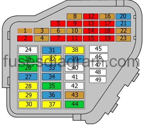
legend (2003 – )
| Fuse | Amps | Circuits protected |
|---|---|---|
| 1 | 5A | Heated washers |
| 2 | 10A | Hazard warning light switch |
| 3 | 5A | Glovebox illumination |
| 4 | 5A | Number plate light(s) |
| 5 | 10A | Air quality sensor Rear roller blind Air-conditioning compressor Air-conditioning control unit Tiptronic switch Telephone Voice control unit Parking assistance Navigation system Oil level sensor Oil temperature sensor Tyre pressure monitor control unit Self-levelling suspension system Automatic gearbox Bulb check control unit |
| 6 | 5A | Central locking |
| 7 | 10A | ABS control unit Steering angle sensor TCS/ESP button Cruise control switch, diesel |
| 8 | 5A | Telephone Telematics |
| 9 | 10A | Heated mirror(s) |
| 10 | 5A | Headlight range control |
| 11 | 10A | Automatic anti-dazzle rear-view mirror |
| 12 | 10A | On-board diagnostic Terminal 30 voltage supply |
| 13 | 10A | Brake light(s) |
| 14 | 10A | Interior monitoring Central locking Seat adjustment memory |
| 15 | 10A | Dash panel insert Additional heater Navigation system CD player Seat and mirror memory Solar cell isolation relay |
| 16 | 5A | Steering angle sensor (ESP) |
| 17 | 10A | Self-levelling suspension system Radio Tyre pressure monitor control unit Parking assistance |
| 18 | 10A | Right main beam |
| 19 | 10A | Left main beam |
| 20 | 15A | Right dipped beam Headlight range control |
| 21 | 15A | Left dipped beam Headlight range control |
| 22 | 5A | Right sidelight Right tail light |
| 23 | 5A | Left sidelight Left tail light |
| 24 | 25A | Wash/wipe system relay Wiper control |
| 25 | 30A | Blower Air-conditioning control unit Climatronic Magnetic clutch Additional heater Solar cell isolation relay |
| 26 | 30A | Heated rear windscreen Air-conditioning control unit Climatronic |
| 27 | 15A | Rear wash/wipe system Heated steering wheel |
| 28 | 20A | Fuel pump |
| 29 | 20A | Ignition coil Motronic control unit Camshaft timing solenoid |
| 30 | 20A | Sliding roof |
| 31 | 15A | Multifunction switch Start inhibitor and reversing light relay Automatic transmission Reversing lights Diagnostic socket Hazard warning light illumination |
| 32 | 20A | Engine management, injectors Cruise control |
| 33 | 15A | Front cigarette lighter Rear cigarette lighter |
| 34 | 15A | Secondary air injection pump relay Solenoid Secondary air inlet valve Turbocharger valve Mass airflow meter Heated oxygen sensor Inlet manifold switch-over valve |
| 35 | 30A | Trailer connector socket |
| 36 | 15A | Front fog light(s) Rear fog light(s) |
| 37 | 20A | Radio Audio amplifier Navigation display Navigation system TV tuner Chip card reader |
| 38 | 20A | Central locking control unit |
| 39 | 15A | Hazard warning lights |
| 40 | 25A | Horn relay |
| 41 | 25A | ABS solenoid |
| 42 | 25A | ABS control unit |
| 43 | 5A | Radio Navigation system |
| 44 | 30A | Heated seat(s) Additional heater Solar cell isolation relay |
| 45 | Spare fuse | |
| 46 | Spare fuse | |
| 47 | Spare fuse | |
| 48 | Spare fuse | |
| 49 | Spare fuse |
Relay box №1 in passenger compartment Audi Allroad.
relay box diagram.
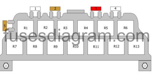
legend.
| Fuse/Relay | Amps | Circuits protected |
|---|---|---|
| 1 | ||
| 2 | 5A | Alarm system (taxi) Fuse B (police cars) (25A also used)Alarm system (taxi) Fuse B (police cars) (25A also used) |
| 3 | 10A | Alarm system or taxi meter Fuse C (police cars) Intercom (special vehicles) (20A also used) |
| 4 | ||
| 5 | 5A | Hydraulic pump Taxi package Fuse E (police cars) (25A also used) |
| R1 | Horn relay | |
| R2 | Alternator relay Alarm system control unit (taxi) Siren relay (police cars) Alarm system (special vehicles) | |
| R3 | Solar cell isolation relay Alarm system (special vehicles) Alarm system control unit (taxi) Siren relay (police cars) | |
| R4 | Start inhibitor and reversing light relay | |
| R5 | Magnetic clutch Additional heater | |
| R6 | Fog light relay Fuel pump relay, TDI | |
| R7 | Multifunction steering wheel | |
| R8 | Multifunction steering wheel | |
| R9 | Bulb check control unit | |
| R10 | Bulb check control unit | |
| R11 | Electric mirror controls | |
| R12 | Electric mirror controls | |
| R13 | Servotronic control unit |
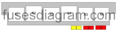
Relay box №2 in passenger compartment Audi Allroad.

relay box diagram.
| Fuse/Relay | Amps | Circuits protected |
|---|---|---|
| 1 | 20A | Steering column adjustment |
| 2 | 10A | Rear roller blind |
| 3 | 10A | Multifunction steering wheel Fuse C (police cars) Boot lid/tailgate (special vehicles) Alarm system 2 (taxi) (20A also used) |
| R1 | Horn relay | |
| R2 | X contact relief relay | |
| R3 | Hydraulic pump relay | |
| R4 | Glow plug relay | |
| R5 | Wash/wipe system relay | |
| R6 | Wash/wipe system relay |
Relay box №3 in passenger compartment Audi Allroad.
relay box diagram.
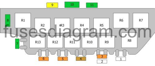
legend.
| Fuse/Relay | Amps | Circuits protected |
|---|---|---|
| 1 | 50A | ABS control unit |
| 2 | Vermin repellent system | |
| 3 | 40A | Cooling fan |
| 4 | 5A | Cooling fan control unit |
| 5 | 40A | Cooling fan |
| 6 | 40A | Self-levelling suspension system |
| 7 | 30A | Passenger’s seat |
| 8 | 30A | Driver’s seat |
| 9 | 20A | 12V socket |
| 10 | 30A | Front windows |
| 11 | 30A | Rear windows |
| R1 | ABS solenoid relay | |
| R2 | Cooling fan relay, stage 2 | |
| R3 | Cooling fan relay Coolant circulation relay | |
| R4 | Cooling fan run-on relay | |
| R5 | Not used | |
| R6 | Self-levelling suspension pump relay | |
| R7 | ABS pump relay | |
| R8 | Coolant shut-off valve relay | |
| R9 | Not used | |
| R10 | Air suspension | |
| R11 | ABS ESP | |
| R12 | Central locking Security system | |
| R13 | Not used |
Relay box №4 in passenger compartment Audi Allroad.

| Fuse/Relay | Amps | Circuits protected |
|---|---|---|
| 1 | 40A | Additional heater |
| 2 | 60A | Brake servo relay or additional heater |
| 3 | Not used | |
| 4 | Not used | |
| R1 | Brake servo relay or additional heater | |
| R2 | Additional heater, blower relay, or solar cell isolation relay | |
| R3 | Additional heater relay |
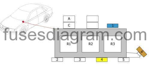
Relay and fuses in the electronics box.
| Fuse/Relay | Amps | Circuits protected |
|---|---|---|
| 1 | 15A | Engine electronics |
| 2 | Not used | |
| 3 | 60A | Glow plugs |
| 4 | 20A | Additional heater |
| 5 | 60A | Glow plugs |
| 6 | 5A | Cooling fan control unit |
| Relay A | Cooling fan | |
| Relay B | Not used | |
| Relay C | Coolant circulation relay | |
| Relay D | Fuel cooling pump relay | |
| R1 | Relay, additional coolant pump | |
| R2 | Secondary air injection pump relay | |
| R3 | Direct injection relay |