For the BMW 6 series (E63/E64) 2003, 2004, 2005, 2006, 2007, 2008, 2009, 2010, 2011 model year.
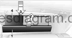
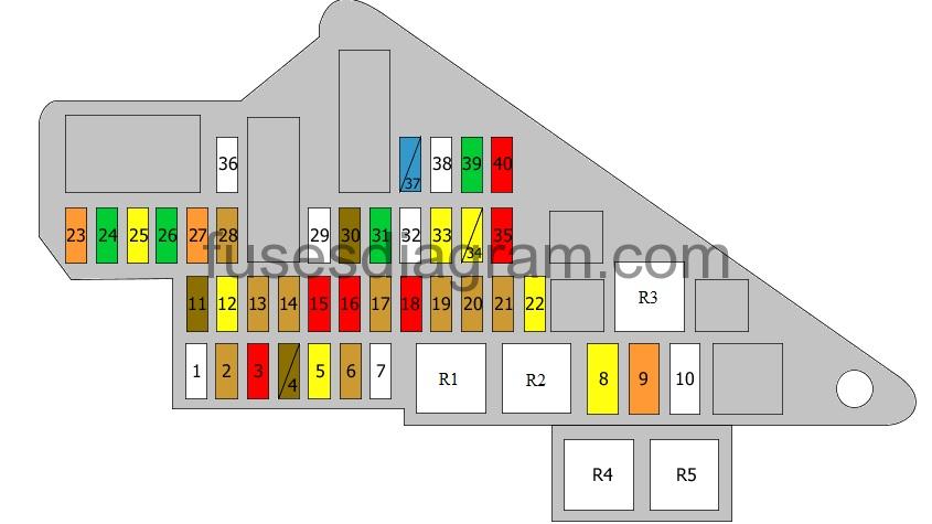
Fuse box in passenger compartment.
fuse box location (in glove compartment) .
Press the button on the back in the center of partition 1 and pull out the partitin upward, arrow 2. Press the coupling downward, arrow 3, and fold the lid 4 forward.
fuse box diagram.
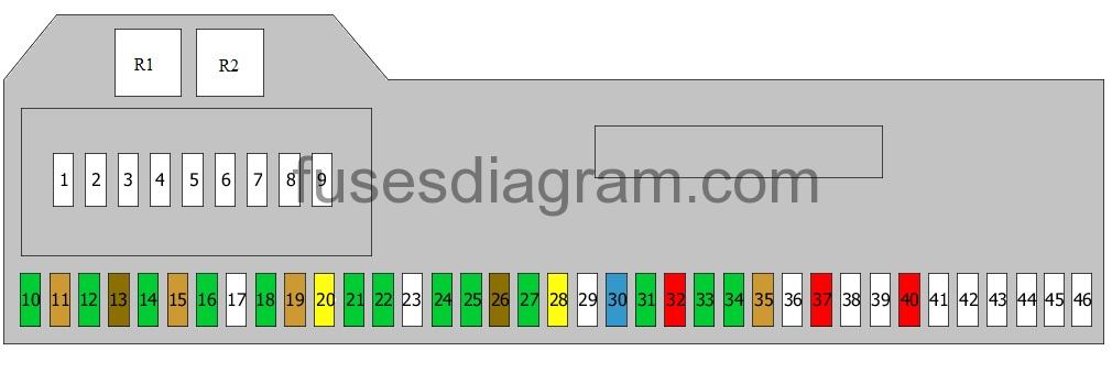
legend.
| Fuses | Amps | Circuits protected |
|---|---|---|
| 1 | 50A | Dynamic stability control (DSC) |
| 2 | Not used | |
| 3 | 40A | Blower |
| 4 | 40A | Power steering |
| 5 | 50A | Light module |
| 6 | 50A | Light module |
| 7 | 50A | Central locking |
| 8 | 60A | Sequential gearbox relay Fuse box in engine compartment, fuse 1 Supply control units |
| 9 | 60A | Cooling fan |
| 10 | 30A | Driver’s door control unit |
| 11 | 5A | Body control unit |
| 12 | 30A | Passenger’s door control unit |
| 13 | 7.5A | Instrument panel |
| 14 | 30A | Driver’s seat control unit Front left seat |
| 15 | 5A | Central locking |
| 16 | 30A | Wiper relay |
| 17 | Not used | |
| 18 | 30A | Headlight washer relay |
| 19 | 5A | Automatic transmission position indicator light(s) (USA) |
| 20 | 20A | Additional heater |
| 21 | 30A | Passenger’s seat control unit Front right seat |
| 22 | 30A | Body control unit |
| 23 | Not used | |
| 24 | 30A | Body control unit |
| 25 | 30A | Dynamic stability control (DSC) |
| 26 | 7.5A | Heating and air conditioning |
| 27 | 30A | Body control unit |
| 28 | 20A | Steering column switches |
| 29 | 29A | Safety and gateway module On-board diagnostic |
| 30 | 15A | Heating and air conditioning |
| 31 | 30A | Driver’s seat control unit |
| 32 | 10A | Dynamic drive |
| 33 | 30A | Passenger’s seat control unit Centre console switch (cabriolet) |
| 34 | 30A | Navigation and multimedia display |
| 35 | 5A | Navigation system (Japan) |
| 36 | Not used | |
| 37 | 10A | Telephone or eject box |
| 38 | Not used | |
| 39 | Not used | |
| 40 | 10A | CD changer |
| 41 | Not used | |
| 42 | Not used | |
| 43 | Not used | |
| 44 | Not used | |
| 45 | Not used | |
| 46 | Not used | |
| R1 | Fuel pump relay Additional relay, fuel pump | |
| R2 | Headlight washer relay |
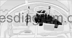
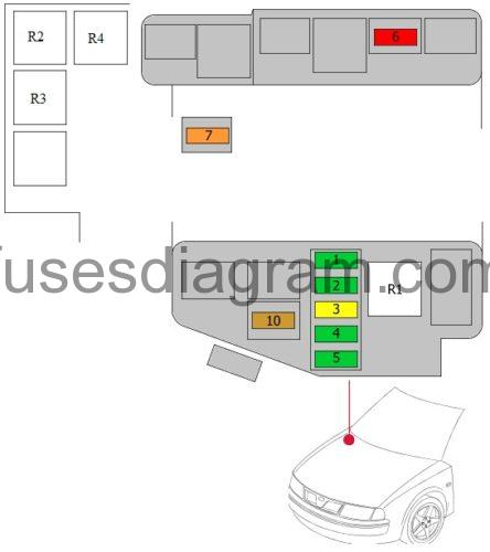
Fuse box in luggage compartment.
Fold the cover under the floor mat upward and remove the bracked for the onboard tool kid. Information on fuse allocation 1 and additional fuse 2 are providet there.
fuse box diagram.
legend.
| Fuses | Amps | Circuits protected |
|---|---|---|
| 1 | Not used | |
| 2 | 5A | Central locking receiver and alarm system |
| 3 | 10A | Micro-power module |
| 4a | 7.5A | Tailgate/boot release Tailgate/boot lock Tailgate/boot release relay |
| 4b | 7.5A | Door control unit, front left Door control unit, front right Door control unit, rear left Door control unit, rear right |
| 5 | 20A | Power save relay Terminal 15 |
| 6 | 5A | Rain sensor |
| 7 | Not used | |
| 8 | 20A | Micro-power module |
| 9 | 40A | Demister |
| 10 | Not used | |
| 11 | 7.5A | Telephone or eject box Micro-power module |
| 12 | 20A | Front cigarette lighter Front 12V socket |
| 13 | 5A | Power save relay Terminal 15 |
| 14 | 5A | Rear-view mirror Parking assistance (PDC) |
| 15 | 10A | Multifunction display Rear information display |
| 16 | 10A | Headset connection module Information display |
| 17 | 5A | Dynamic stability control unit |
| 18 | 10A | Video system Antenna |
| 19 | 5A | Centre console unit Seat adjustment |
| 20 | 5A | Parking assistance (PDC) |
| 21 | 5A | Headlight(s) |
| 22 | 20A | Rear wiper relay |
| 23 | 40A | Convertible roof |
| 24 | 30A | Trailer control unit |
| 25 | 20A | Trailer connector socket |
| 26 | 30A | Air suspension compressor relay Air suspension |
| 27 | 40A | Tailgate/boot release |
| 28 | 5A | TV tuner Radio remote display |
| 29 | Not used | |
| 30 | 7.5A | Ride height control |
| 31 | 30A | Antenna amplifier |
| 32 | Not used | |
| 33 | 20A | Cigarette lighter Rear 12V socket 12V socket in luggage compartment |
| 34a | 20A | Sunroof |
| 34b | 20A | Convertible roof |
| 35 | 10A | Cruise control |
| 36 | Not used | |
| 37a | 15A | Transmission control unit |
| 37b | 15A | Sequential gearbox |
| 38 | Not used | |
| 39 | 30A | Centre console unit |
| 40 | 10A | Telephone or eject box Automatic transmission gear selector illumination Automatic transmission selector handle |
| R1 | Terminal 15 voltage supply relay | |
| R2 | Terminal 30 voltage supply relay | |
| R3 | Demister relay | |
| R4 | Rear window(s), relay | |
| R5 | Rear window(s), relay |
Fuse box in engine compartment.
| Fuses | Amps | Circuits protected |
|---|---|---|
| 1 | 30A | Ignition coils 1 – 3 Ignition coils 4 – 6 |
| 2 | 30A | Camshaft timing solenoid Camshaft sensor MAP-controlled engine cooling thermostat Coolant pump |
| 3 | 20A | Crankshaft position sensor Mass airflow meter DME Oil quality sensor Fuel tank cap Variable resonance inlet manifold switch-over valve |
| 4 | 30A | Oxygen sensor in front of the catalytic converter Oxygen sensor 2 in front of the catalytic converter Oxygen sensor behind the catalytic converter Oxygen sensor 2 behind the catalytic converter Sequential gearbox Crankcase heater |
| 5 | 30A | Injector relay |
| 6 | 10A | Thermoswitch, radiator Fuel tank leak diagnosis Secondary air pump relay Mass airflow meter Electronics box (E-box) cooling fan Exhaust manifold flap |
| 7 | 40A | Variable valve timing relay |
| 10 | 5A | Crankcase heater relay |
| R1 | DME relay | |
| R2 | Crankcase heater relay | |
| R3 | Wiper relay or not used | |
| R4 | Variable valve timing relay |