
For the Honda CR-V 2007, 2008, 2009, 2010, 2011, 2012 model year.
Fuse box in passenger compartment.
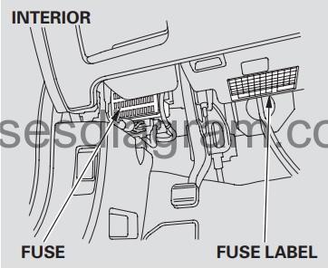
fuse box location.
The interior fuse box is located under the dashboard on the driver’s side. The fuse label is attached under the steering column.
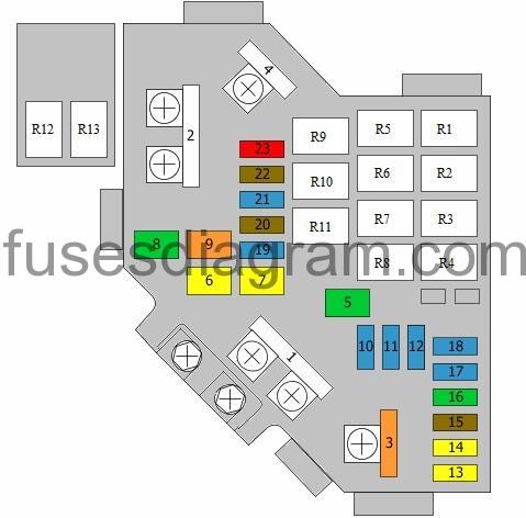
fuse box diagram (pre 2009).
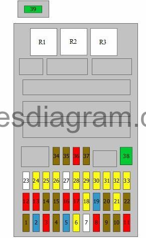
legend.
| Fuse | Amps | Circuits protected |
|---|---|---|
| 1 | 7,5A | Power windows, main switch Rain and light sensor Headlight levelling switch Headlight levelling |
| 2 | 15A | Engine control unit Immobiliser control unit |
| 3 | 10A | Alternator Brake pedal switch Detector, electrical load Mass airflow meter |
| 4 | 7,5A | Yaw rate sensor |
| 5 | 15A | Heated seats |
| 6 | 20A | Front fog light(s) Front fog light relay |
| 7 | 25A | Not used |
| 8 | 10A | Adaptive headlights or headlight levelling control unit Multiplex control unit Rear wiper motor |
| 9 | 7,5A | Pretensioner Supplemental restraint system (SRS) control unit |
| 10 | 7,5A | Reversing light switch Multiplex control unit Gear selector switch |
| 11 | 10A | Supplemental restraint system (SRS) control unit |
| 12 | 10A | Right main beam |
| 13 | 10A | Left main beam |
| 14 | 7,5A | Dashboard illumination Navigation and multimedia unit |
| 15 | 7,5A | Parking light Number plate lights Tail lights Optional connector |
| 16 | 10A | Right dipped beam Headlight washer control unit (15A also used) |
| 17 | 10A | Left dipped beam (15A also used) |
| 18 | 20A | Multiplex control unit |
| 19 | 15A | Multiplex control unit |
| 20 | 7,5A | Multiplex control unit |
| 21 | 20A | Multiplex control unit (30A also used) |
| 22 | 7,5A | Adaptive cruise control unit Cruise control unit Radar sensor Adaptive headlights or headlight levelling control unit |
| 23 | 25A | Not used |
| 24 | 20A | Sunshade Sunshade control unit |
| 25 | 20A | Multiplex control unit |
| 26 | 20A | Power windows, main switch |
| 27 | 25A | Not used |
| 28 | 20A | Rear accessory socket |
| 29 | 20A | Front accessory socket |
| 30 | 20A | Power window switch, front passenger |
| 31 | 20A | Accessory socket |
| 32 | 20A | Switch, rear right power window(s) |
| 33 | 20A | Switch, rear left power window(s) |
| 34 | 7,5A | Accessory socket relay Audio unit Handsfree telephone control unit |
| 35 | 7,5A | Multiplex control unit Key lock |
| 36 | 10A | Climate control unit Heating and air conditioning control unit Electric mirrors Recirculation control motor Fuse and relay box in engine compartment, relays R1, R5 – R9 Cooling fan relay Heated seats |
| 37 | 7,5A | Multiplex control unit or not used |
| 38 | 30A | Multiplex control unit |
| 39 | 30A | Headlight washer control unit |
| R1 | Power window relay | |
| R2 | Fuel pump relay | |
| R3 | Starter blocker relay |
Fuse box diagram (since 2010).
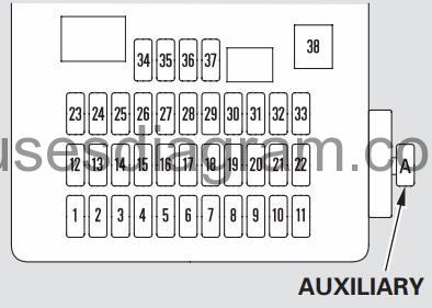
legend.
No. | Amps. | Circuits Protected |
|---|---|---|
1 | 7.5 A | Power Window Relay |
2 | 15 A | Fuel Pump |
3 | 10 A | ACG |
4 | 7.5 A | ABS/VSA |
5 | (15 A) | Heated Seats* |
6 | — | Not used |
7 | — | Not used |
8 | 10 A | Rear Wiper |
9 | 7.5 A | ODS (Occupant Detection System) |
10 | 7.5 A | Meter |
11 | 10 A | SRS |
12 | 10 A | Right Headlight High Beam |
13 | 10 A | Left Headlight High Beam |
14 | 7.5 A | Small Light (Interior) |
15 | 7.5 A | Small Light (Exterior) |
16 | 10 A | Right Headlight Low Beam |
17 | 10 A | Left Headlight Low Beam |
18 | 20 A | Main Headlight High Beam |
19 | 15 A | Small Lights MAIN |
20 | 7.5 A | TPMS |
21 | 20 A | Main Headlight Low Beam |
22 | — | Not used |
23 | — | Not used |
24 | (20 A) | Moonroof* |
25 | 20 A | Door Lock |
26 | 20 A | Front Left Power Window |
27 | — | Not used |
28 | 15 A | Rear Accessory Power Socket |
29 | 15 A | Front Accessory Power Socket |
30 | 20 A | Front Right Power Window |
31 | (15 A) | Accessory Power Socket* (in the Console Compartment/ on the Center Table) |
32 | 20 A | Rear Right Power Window |
33 | 20 A | Rear Left power window |
34 | 7.5 A | ACC Radio |
35 | 7.5 A | ACC Key lock |
36 | 10 A | НАС |
37 | 7.5 A | Daytime Running Lights |
38 | 30 A | Front Wiper |
A | 10 A | VB SOL |
В | — | — |
Additional relay in passenger compartment (pre 2009).
Relay R1 – Alarm horn relay
Relay R2 – Daylight running system relay or not used
Relay R3 – Front accessory socket
Relay R4 – Rear accessory socket
Relay R5 – Front fog light relay
Relay R6 – Accessory socket
Additional relay in passenger compartment (since 2010).
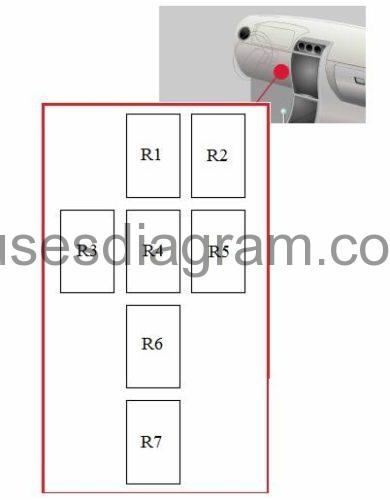
Relay R1 – Rear accessory socket
Relay R2 – Accessory socket
Relay R3 – Transmission control relay
Relay R4 – Front accessory socket
Relay R5 – Front fog light relay
Relay R6 – Alarm horn relay
Relay R7 – Daylight running system relay or not used
Additional relay in passenger compartment (since 2010), RHD.
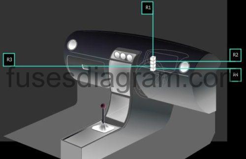
Relay R1 – Rear accessory socket
Relay R2 – Front accessory socket
Relay R3 – Accessory socket
Relay R4 – Front fog light relay
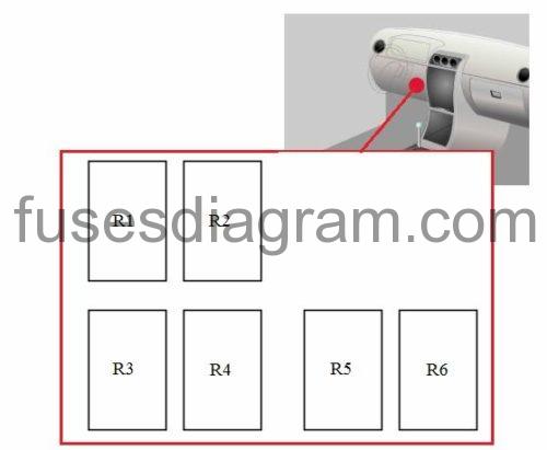
Additional relay in passenger compartment.
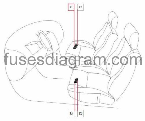
Relay R1 – Heated front passenger’s seat
Relay R2 – Heated front passenger’s seat
Relay R3 – Heated driver’s seat
Relay R4 – Heated driver’s seat
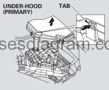
Fuse box in engine compartment.
fuse box location.
The under-hood fuse box is on the driver’s side. To open it, push the tabs as shown.
fuse box layout.
legend.
| Fuse | Amps | Circuits protected |
|---|---|---|
| 1 | 100A | Battery Power distribution ESP control unit (70A also used) |
| 2 | 50A | Ignition switch Fuse and relay box in passenger compartment, fuses 5 – 7, 27 – 29, 31 (80A also used) |
| 3 | 40A | ABS/ESP control unit (20A also used) |
| 4 | 50A | Fuse and relay box in passenger compartment, fuses 18 – 21 Fuse and relay box in passenger compartment, fuses 24 – 26, 30, 32, 33, relay R1 (40A also used) |
| 5 | 30A | Pretensioner |
| 6 | 20A | Air-conditioning condenser fan |
| 7 | 20A | Cooling fan |
| 8 | 30A | Heated mirror relay Heated rear windscreen |
| 9 | 40A | Blower motor |
| 10 | 15A | Multiplex control unit |
| 11 | 15A | Air-fuel ratio sensor relay Air-fuel ratio sensor |
| 12 | 15A | Cruise control relay Alarm horn relay Multiplex control unit |
| 13 | 20A | Driver’s seat adjustment switch |
| 14 | 20A | Driver’s seat adjustment switch Driver’s seat lumbar support switch |
| 15 | 7,5A | Air-conditioning fan relay Engine oil level sensor or not used |
| 16 | 30A | Pretensioner |
| 17 | 15A | Audio unit Subwoofer |
| 18 | 15A | Ignition coils Ignition coil relay |
| 19 | 15A | Electronic throttle control Main relay, No. 1 Crankshaft position sensor Camshaft position sensor Engine control unit Fuel pump relay |
| 20 | 7,5A | Air-conditioning compressor clutch |
| 21 | 15A | Engine control unit |
| 22 | 7,5A | Rain and light sensor Cargo light(s) Interior light Map reading light(s) Ignition key light Vanity light |
| 23 | 10A | Alarm siren Audio unit Navigation and multimedia unit Data link connector Dashboard control unit Handsfree telephone control unit Immobiliser control unit Ultrasonic sensor |
| R1 | Fan control | |
| R2 | Rear windscreen wiper | |
| R3 | Fuel injection relay | |
| R4 | Ignition coil relay | |
| R5 | Air-conditioning condenser fan relay | |
| R6 | Blower motor relay | |
| R7 | Heated rear windscreen relay | |
| R8 | Air-conditioning compressor clutch relay | |
| R9 | Cooling fan relay | |
| R10 | Electronic throttle control | |
| R11 | Main relay, No. 1 | |
| R12 | Cruise control relay | |
| R13 | Heated mirror relay |