For the Honda HR-V 1999, 2000, 2001, 2002, 2003, 2004, 2005, 2006 model year.
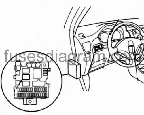
Fuse box in passenger compartment.
fuse box location.
fuse box diagram.
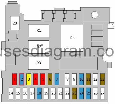
legend.
| Fuse | Amps | Circuits protected |
|---|---|---|
| 1 | 10A | SRS control unit |
| 2 | 15A | SRS control unit Inertia switch Programmed fuel injection, main relay |
| 3 | 20A | Windscreen wash/wipe system |
| 4 | 10A | Power window relay Rear wash/wipe system Headlight levelling control unit Headlight levelling switch |
| 5 | 10A | Integrated control unit Reversing lights Direction indicators Hazard warning light relay |
| 6 | 7,5A | Battery sensor (ELD) module Instrument panel Vehicle speed sensor (VSS) Keyless entry control unit Engine control unit Powertrain control unit (PCM) Evaporative canister purge solenoid(s) Heated oxygen sensor(s) Alternator Seat belt and vehicle speed warning control unit (SA) Clock |
| 7 | 15A | Distributor |
| 8 | not used | |
| 9 | not used | |
| 10 | 15A | Heated rear windscreen |
| 11 | 7,5A | Cooling fan relay Blower motor relay Condenser fan relay Air-conditioning compressor relay Air-conditioning switch Air-conditioning thermostat ABS modulator unit Electric mirrors Heated seats, main relay |
| 12 | not used | |
| 13 | 7,5A | Engine control unit Powertrain control unit (PCM) Programmed fuel injection, main relay |
| 14 | not used | |
| 15 | not used | |
| 16 | not used | |
| 17 | not used | |
| 18 | 15A | Audio system Cigarette lighter |
| 19 | not used | |
| 20 | not used | |
| 21 | not used | |
| 22 | not used | |
| 23 | 7,5A | Integrated control unit Immobiliser control unit Buzzer Clock Engine control unit Powertrain control unit (PCM) Interior light(s) |
| 24 | 15A | Audio system |
| 25 | 15A | Keyless entry control unit |
| 26 | not used | |
| 27 | not used | |
| 28 | not used | |
| R1 | Power window relay | |
| R2 | Tail light(s) relay | |
| R3 | Relay, heated seats Shift lock relay | |
| R4 | Direction indicators Hazard warning light relay |
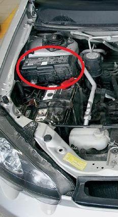
Fuse box in engine compartment.
fuse box location.
fuse box layout.

legend.
| Fuse | Amps | Circuits protected |
|---|---|---|
| 1 | 80A | Battery Power distribution |
| 2 | 50A | Ignition switch, BAT |
| 3 | 20A | Right headlight Main beam indicator light |
| 4 | 7,5A | Rear fog light(s) |
| 5 | 20A | Left headlight |
| 6 | 7,5A | Tail light(s) Number plate light(s) Instrument panel lighting Illumination, switch(es) Integrated control unit Illumination brightness control Audio system Clock Front parking lights Optional connector (10A also used) |
| 7 | 15A | ABS modulator unit Transmission interlock solenoid (automatic transmission) Brake lights Transmission control unit Engine control unit (10A also used) |
| 8 | 20A | ABS modulator unit |
| 9 | 15A | Hazard warning light switch Hazard warning light relay (10A also used) |
| 10 | 40A | ABS modulator unit |
| 11 | 20A | Passenger’s power window Power window relay |
| 12 | 20A | Driver’s side power window Power window switches |
| 13 | Not used | |
| 14 | 30A | Fuse box in passenger compartment, fuses 23 – 25 Optional connector |
| 15 | 20A | Heated seat(s) |
| 16 | 40A | Blower motor |
| 17 | 20A | Cooling fan |
| 18 | 20A | Condenser fan Air-conditioning compressor |
| 19 | 15A | Programmed fuel injection, main relay Data link connector |
| R1 | Headlight relay 1 | |
| R2 | Headlight relay 2 | |
| R3 | Horn relay | |
| R4 | Blower motor relay | |
| R5 | Condenser fan relay | |
| R6 | Cooling fan relay | |
| R7 | Air-conditioning compressor clutch relay | |
| ELD | Battery sensor (ELD) module |