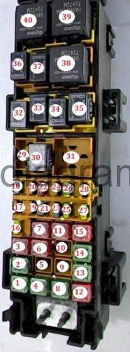
For the Jeep Grand Cherokee second generation 1999, 2000, 2001, 2002, 2003, 2004 model year.
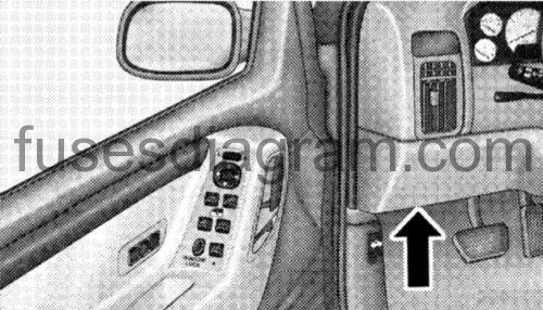
Fuse box located.
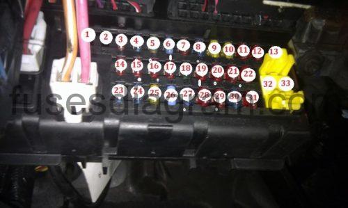
The fuse panel is on the lower instrument panel just to the left of the steering column. A label is stamped on the fuse panel cover to identify each fuse for ease of replacement.
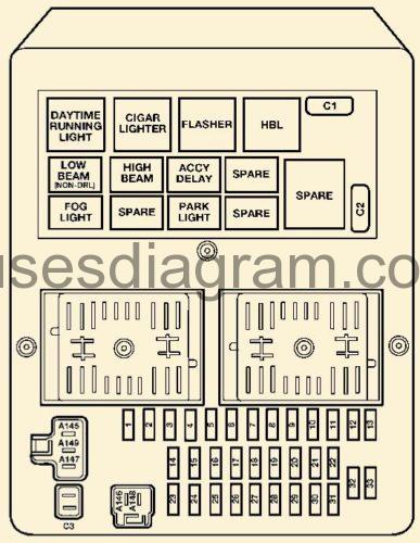
Fuse box diagram.
legend.
Cavity | Fuse | Description |
1 | Spare |
|
2 | Spare |
|
3 | 10 Amp Red | Headlight High Beam Left |
4 | 15 Amp Lt. Blue | Flasher |
5 | 25 Amp Natural | Radio/Amplifier |
6 | 15 Amp Lt. Blue | Park Lights |
7 | 10 Amp Red | Interior Lights |
8 | 15 Amp Lt. Blue | Overhead Console, Rear Wiper, IP Lights, Rear Flipper Glass Solenoid |
9 | 20 Amp Yellow | Power Outlets |
10 | 20 Amp Yellow | Adjustable Pedals |
11 | 10 Amp Red | Rear Window Defroster Indicator |
12 | 10 Amp Red | Auto Shut Down Relay/ "Fuel" |
13 | Spare |
|
14 | 10 Amp Red | Headlight Low Left |
15 | 10 Amp Red | Headlight Low Right |
16 | 10 Amp Red | Headlight High Right |
17 | 10 Amp Red | Instrument Cluster, Diagnostic Connector |
18 | 30 Amp | Trailer Tow |
19 | 10 Amp Red | Antilock Brakes |
20 | 10 Amp Red | Ignition Run |
21 | 10 Amp Red | Ignition Run/Start – PDC |
22 | 10 Amp Red | Ignition Run/Start |
23 | 15 Amp Lt. Blue | Brake Switch |
24 | 15 Amp Lt. Blue | Fog Lamps |
25 | 20 Amp Yellow | Accessory Delay Relay (Sunroof) |
26 | 15 Amp Lt. Blue | Cigar |
27 | 15 Amp Lt. Blue | Rear Fog Lamps (If Equipped) |
28 | 10 Amp Red | Body Control Module, Acc/ Run |
29 | 10 Amp Red | Rear Wiper Switch, Washer Motors |
30 | 15 Amp Lt. Blue | Radio |
31 | 10 Amp Red | Ignition Start |
32 | 10 Amp Red | Ignition Run/Start-Airbag |
33 | 10 Amp Red | Ignition Run/Only – Airbag |
C1 | 20 Amp | Wiper (Circuit Breaker) |
C2 | 20 Amp | Seats (Circuit Breaker) |
C3 |
| Spare |
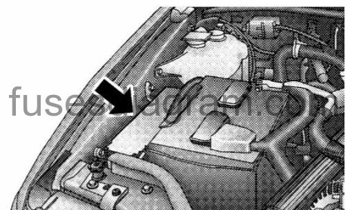
Underhood Fuses (Power Distribution Center) Jeep Grand Cherokee 1999-2004.
Your vehicle is equipped with an electrical power distribution center located in the engine compartment near the battery. This power center houses plug-in “Cartridge” fuses which replace in-line fusible links. The power center also contains “Mini” fuses and plug-in full and mini ISO relays. A label inside the latching cover of the center identifies each component for ease of replacement, if necessary.
fuse box diagram.
1. Blower motor 40A
2. Junction bus power 40A
3. Junction bus pwr lamps 50A
4. ABS pump 40A
5. TCM power 30A
6. ASD 30A
7. Junction block pwr 50A
8. Ignition starter 40A
9. (not used)
10. Radiator fan relay 40A
11. (Empty, for IOD fuse storage)
12. Power windows 50A
13. OSS pump 60A
14. Ignition switch 40A
15. JB power 50A (IOD)
16. 02 sensor 15A
17. Cluster / Data link 10A
18. Horn 15A
19. PCM 10A
20. OSS module 20A
21. AC clutch 15A
22. ECM 10A
23. Cabin heater relay 15A
24. Fuel pump 20A
25. ABS main relay 20A
26. Injectors 15A
27. Rear pwr outlet 20A
28. TCM 15A
29. Fuel pump
30. Starter motor
31. TCM
32. Wiper On/Off
33. Wiper Hi-Low
34. Rear 02 sensor/Viscous cabin heater
35. Backup lamp
36. AC clutch
37. Horn
38. Auto Shut Down
39. OSS module/Glow plug
40. OSS pump/Glow plug

