For the Jeep Grand Cherokee (WK, WH) 2005, 2006, 2007, 2008, 2009, 2010, 2011 model year.
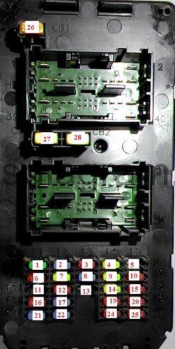
Fuse box in passenger compartment.
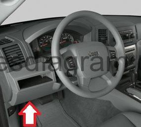
The fuse panel is on the lower instrument panel just to the left of the steering column.
fuse box diagram.
legend.
F1 | (30A) Audio system |
F2 | (15A) Sunroof |
F3 | (10A) Htd Mirror (EBL) |
F4 | (20A) Auxiliary power socket |
F5 | – |
F6 | (10A) Supplementary restraint system (SRS) |
F7 | (20A) Central locking system |
F8 | (15A) |
F9 | (20A) Auxiliary power socket |
F10 | (10A) Heated rear window |
F11 | – |
F12 | (10A) Interior lamps |
F13 | – |
F14 | (20A) Cigarette lighter |
F15 | (10A) Tyre pressure monitoring system |
F16 | (10A) Upper & Lower, Switch Bank, Diag. Connector, Cluster (B+) |
F17 | (15A) Instrument panel |
F19 | (10A) Starting system |
F20 | (10A) Supplementary restraint system (SRS) |
F21 | (15A) |
F22 | (15A) Rear screen wiper |
F24 | (10A) Transmission |
F25 | (10A) Shifter Assy (BTSI), Trans. Case Switch, ESP/ABS, Trailer Sway Damp Relay |
F26 | (20A) Trailer/Cycle Wipers |
F27 | (20A) Trailer/ Cycle Window |
F28 | (20A) Trailer/Cycle seats |
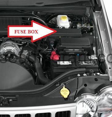
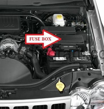
Fuse box in engine compartment Jeep Grand Cherokee (WK).
Power distribution center.
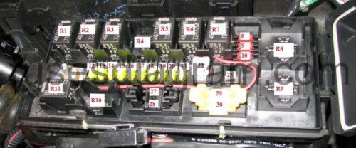
fuse box layout (pre 2007).
legend.
R1 | Heater blower relay |
R2 | Ignition main circuits relay |
R3 | PTC (diesel) |
R4 | PTC (diesel) |
R5 | Starter motor relay |
R6 | Transmission control module (TCM) relay |
R7 | AC compressor clutch relay |
R8 | Fuel pump (FP) relay |
R9 |
|
R10 | – |
R11 | TC (diesel) |
F1 | (40A) AC/heater blower motor |
F2 | (30A) Auxiliary power socket |
F3 | (30A) Rear screen wiper |
F4 | (30A)ABS/ESP system |
F5 | (50A) Auxiliary heater |
F6 | (50A) Auto Shut Down (ASD) |
F7 | (30A) Fascia fuse box/relay plate |
F8 | (40A) Fascia fuse box/relay plate |
F9 | – |
F10 | (40A) Starting system |
F11 | (30A) Cigarette lighter |
F12 | (40A) Heated rear window |
F13 | (40A) Junction Block (JB) Power |
F14 | (50A) Auxiliary heater |
F15 | (50A) Auxiliary heater |
F16 | (25A) Diesel: Engine management system |
F17 | – |
F18 | (20A) EATX/AC Clutch |
F19 | (20A) Ignition switch |
F20 | (20A) Transmission control module (TCM) |
F21 | (30A)ABS/ESP system |
F22 |
|
F23 | (20A) Differential |
F24 | (20A) Fuel pump (FP) |
F25 | (20A) Differential |
F26 | (15A) Engine management system |
F27 | (15A) Stop lamps |
F28 | (25A) Diesel: Engine management system |
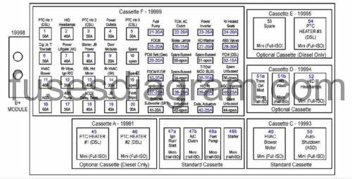
fuse box layout (since 2007).
Cavity | Fuse | Description |
1 | 50 Amp | PTC Heater 1 (Diesel Only) |
2 | 40 Amp | HID Headlamps |
3 | 50 Amp | PTC Heater 2 (Diesel Only) |
4 | 30 Amp | Power Outlets |
5 | 50 Amp | PTC Heater 3 (Diesel Only) |
6 | 30 Amp | Cig Lighter, Trail Tow Batt |
7 | 40 Amp | – |
8 | 40 Amp | Starter, JB Power |
9 | 20 Amp | Front Power Windows |
10 | – | – |
11 | 40 Amp | HVAC Blower |
12 | 30 Amp | Rear Wiper, Ign R/O |
13 | 40 Amp | Rear Window Defroster (EBL)/Heated Mirror |
14 | 30 Amp | Rear HVAC (If Equipped) |
15 | – | – |
16 | 50 Amp | ASD |
17 | 30 Amp | ABS Pump |
18 | 40 Amp | Accessory Delay, Seats |
19 | 40 Amp | JB Power |
20 | 30 Amp | Wiper Motor |
21 | 20 Amp | Fuel Pump |
22 | 20 Amp | TCM, A/C Clutch |
23 | 25 Amp | Power Inverter |
24 | 20 Amp | Rear Heated Seats |
25 | 20 Amp | Final Drive Control Module (FDCM) |
26 | 15 Amp | Brake Lamps |
27 | 20 Amp | HD Washer (If Equipped) |
28 | 30 Amp | ABS Valves |
29 | 20 Amp | PCM Batt (Gasoline Only) |
30 | – | – |
31 | – | – |
32 | 15 Amp | Powertrain Control Module (Diesel Only) |
33 | 20 Amp | Final Drive Control Module (FDCM) E-Diff |
34 | – | – |
35 | 20 Amp | Trail-Tow Mod (BUX Only) |
36 | – | – |
37 | 20 Amp | Ignition Switch |
38 | 20 Amp | HID Left |
39 | 20 Amp | HID Right |
40 | 25 Amp | Next Generation Controller (NGC), Injectors |
41 | 20 Amp | Subwoofer (SRT Only) |
42 | – | – |
43 | 25 Amp | Coils, Actuators |
44 | – | – |
Integrated Power Module.
fuse box diagram.
R1 | Relay wiper on/off |
Re | Relay wiper high/low |
R3 | Horn relay |
R4 | Rear fog lamp relay |
R5 | Indicator relay, left |
R6 | Indicator relay, right |
R7 | Parking lamp relay |
R8 | Relay radiator fan high |
R9 | Relay radiator fan low |
R10 | Pedal box adjustment relay |
R11 | Front fog lamp relay |
F8 | (10A) Parking lamps |
F9 | (10A) Parking lamps |
F10 | (10A) Parking lamps |
F12 | (20A) Multifunction control module |
F13 | (20A) Multifunction control module |
F14 | (20A) Pedal box adjustment system |
F15 | (20A) Front fog lamps |
F16 | (20A) Horn |
F17 | (20A) Rear fog lamps |
F18 | (20A) Multifunction control module |
F19 | (20A) Indicators |
F20 | (20A) Multifunction control module |
F21 | (20A) Indicators |
F22 | (30A) Differential |
F23 | (50A) Engine coolant blower motor |
F27 | (15A) Ignition Off Draw (IOD) #1 — Intrusion Module, Satellite Video, Steering Con-trol Module |
F28 | (20A) Audio system |
F29 | (10A) Supplementary restraint system (SRS) |
F30 | (10A) Supplementary restraint system (SRS) |

