
For the Suzuki Grand Vitara 2005, 2006, 2007, 2008, 2009, 2010, 2011, 2012, 2013, 2014 model year.
Fuse box in passenger compartment.
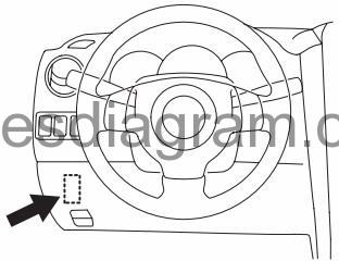
Fuse box location.
The fuse box is located under the driver’s side of the dashboard.
fuse box diagram.
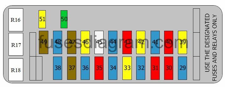
legend.
| Fuse | Amps | Circuits protected |
|---|---|---|
| 29 | 15A | SDM |
| 30 | 10A | ABS control unit ESP control unit Steering angle sensor Reversing light switch |
| 31 | 10A | Transmission range sensor Left headlight levelling actuator Right headlight levelling actuator Automatic headlight levelling Headlight levelling switch |
| 32 | 15A | Air-conditioning compressor relay Driver’s seat heater switch Passenger’s seat heater switch Sliding roof control unit Heater blower relay |
| 33 | 20A | Combination switch Windscreen wash/wipe system Rear wash/wipe system Headlight washer module |
| 34 | 15A | Cigarette lighter |
| 35 | 10A | Brake light switch Steering column switches |
| 36 | 15A | Accessory socket 1 Accessory socket 2 |
| 37 | 7,5A | Combination switch Rear fog light(s) |
| 38 | 15A | Brake light switch |
| 39 | 20A | Generator Ignition coil Noise filter Engine control unit Fuel pump relay Heated oxygen sensor relay Automatic transmission relay 4WD control unit |
| 40 | 10A | Body control unit (BCM) Combination meter Direction indicator relay Air-conditioning control unit |
| 41 | 15A | Cruise control relay Body control unit (BCM) Mirror(s) Engine control unit Subwoofer system Multifunction display |
| 42 | 20A | Body control unit (BCM) |
| 43 | 10A | Tail light(s) relay |
| 44 | 15A | Audio Cruise control Engine control unit DLC TCM Body control unit (BCM) Multifunction display Combination meter Interior light(s) Rear interior light(s) Control lights Air-conditioning control unit Steering angle sensor |
| 45 | 25A | Sliding roof |
| 46 | 20A | Not used |
| 47 | 7,5A | Starter motor relay |
| 48 | 15A | Direction indicator relay |
| 49 | 7,5A | Vanity mirror(s) illumination |
| 50 | 30A | Power windows, main switch Front windows Rear windows |
| 51 | 20A | Not used or Power windows |
| R1 | Tail light relay | |
| R2 | Cruise control relay | |
| R3 | Shift lock relay |
Fuse box in engine compartment.
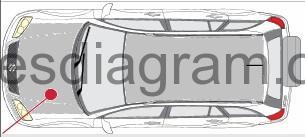
fuse box location.
fuse box layout.
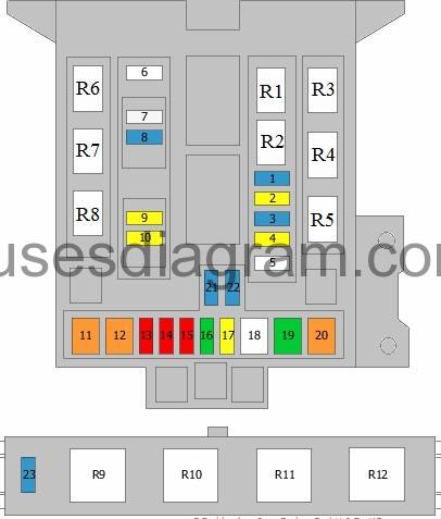
legend.
| Fuse | Amps | Circuits protected |
|---|---|---|
| 1 | 15A | Air-conditioning compressor relay Or Horn |
| 2 | 20A | Heated oxygen sensor relay |
| 3 | 15A | Throttle control motor relay |
| 4 | 20A | Parking lock position (automatic transmission) |
| 5 | not used | |
| 6 | not used | |
| 7 | 25A | Relay, rear demister |
| 8 | 15A | Horn relay |
| 9 | 20A | Front fog light relay |
| 10 | 20A | Heated mirror relay |
| 11 | 40A | Ignition switch |
| 12 | 40A | Starter relay |
| 13 | 10A | Dipped beam Main beam |
| 14 | 10A | Right main beam Main beam relay |
| 15 | 10A | Dipped beam relay Left dipped beam |
| 16 | 30A | Supply pump (CL) |
| 17 | 20A | Main relay |
| 18 | 50A | ABS control unit |
| 19 | 30A | ABS control unit |
| 20 | 40A | Heater relay |
| 21 | 15A | Dipped beam relay Right dipped beam |
| 22 | 15A | Dipped beam relay Left dipped beam |
| 23 | 15A | Not used |
| R1 | Compressor | |
| R2 | Heated oxygen sensor relay | |
| R3 | Fuel pump relay Additional relay, fuel pump | |
| R4 | Main relay | |
| R5 | Heater motor | |
| R6 | Starter motor relay | |
| R7 | Main beam relay | |
| R8 | Dipped beam relay | |
| R9 | Throttle control motor relay | |
| R10 | Heater relay | |
| R11 | Heater relay | |
| R12 | Heater relay |
Main fuse box in engine compartment.
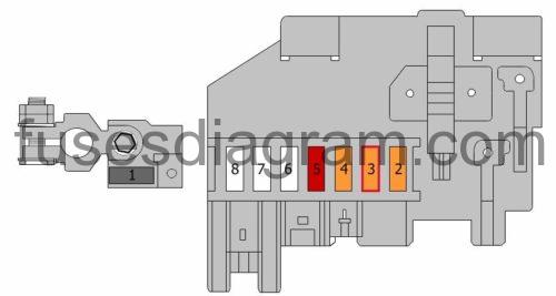
| Fuse | Amps | Circuits protected |
|---|---|---|
| 1 | 80A | Main power supply and ground circuit Battery Main fuse box in engine compartment |
| 2 | 40A | Coolant heater relay 2 |
| 3 | 40A | Coolant heater relay 1 |
| 4 | 40A | 4WD control unit |
| 5 | 50A | Ignition switch |
| 6 | 60A | Fuse box in engine compartment Dipped beam relay Passenger compartment |
| 7 | Not used Or Fuse box in engine compartment | |
| 8 | Not used Or Fuse box in engine compartment |