For the Suzuki Swift 2004, 2005, 2006, 2007, 2008, 2009, 2010 model year.
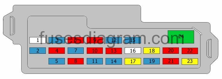
Fuse box in passenger compartment.
Fuse box diagram.
legend
| Fuse | Amps | Circuits protected |
|---|---|---|
| 1 | not used | |
| 2 | 15A | Combination switch Windscreen wash/wipe system Rear wash/wipe system Daylight running system (DRL) |
| 3 | 15A | Control unit Fuel pump relay Generator Heated oxygen sensor 1 Heated oxygen sensor 2 Ignition coils Glow plug control unit Clutch switch Air-conditioning compressor relay Mass airflow meter |
| 4 | 10A | Parking lock position (automatic transmission) Power steering control unit Throttle control motor relay Brake light switch |
| 5 | 15A | Heated driver’s seat Heated passenger’s seat |
| 6 | 10A | Reversing light switch Switch module Air-conditioning control unit Transaxle range switch Left headlight levelling actuator Right headlight levelling actuator Headlight levelling switch Control unit PTC |
| 7 | 15A | Airbag SDM |
| 8 | 10A | Heater relay |
| 9 | 10A | Body control unit (BCM) Combination meter Flasher relay |
| 10 | 10A | ABS control unit |
| 11 | 15A | Rear fog light(s) |
| 12 | 15A | Mirror(s) Body control unit (BCM) |
| 13 | 10A | Combination switch |
| 14 | 15A | Audio Body control unit (BCM) Combination meter DLC Control unit Interior light(s) Luggage compartment light(s) Main power supply and ground circuit Multifunction display TCM |
| 15 | 15A | Cigarette lighter Audio Multifunction display Control unit |
| 16 | not used | |
| 17 | 20A | Relay, rear demister |
| 18 | 20A | Body control unit (BCM) |
| 19 | 15A | Horn relay Flasher relay |
| 20 | 10A | Control unit |
| 21 | 10A | Throttle control motor relay High Intensity Discharge (HID) |
| 22 | 10A | Park/neutral position switch (automatic transmission) Starter motor relay |
| 23 | 20A | |
| 24 | 30A | Window switches Rear right window Rear left window |
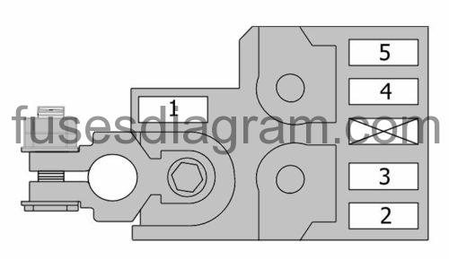
Fuse box in engine compartment.
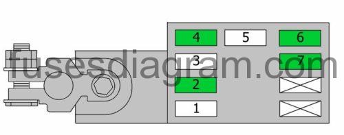
Main fuse box (gasoline).
| Fuse | Amps | Circuits protected |
|---|---|---|
| 1 | 80A | Main power supply and ground circuit Battery Generator |
| 2 | 50A | Headlight(s) |
| 3 | 50A | Ignition switch Fuse box in passenger compartment |
| 4 | 80A | Fuse box in engine compartment |
| 5 | 80A | Fuse box in engine compartment |
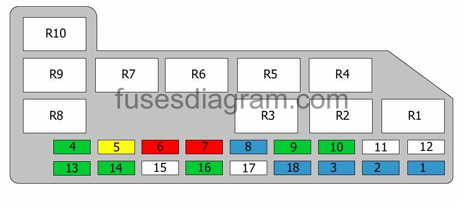
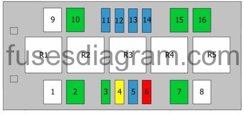
Fuse box diagram (engine compartment – gasoline).
legend.
| Fuse | Amps | Circuits protected |
|---|---|---|
| 1 | 15A | Right headlight |
| 2 | 15A | Left headlight |
| 3 | 15A | Front fog light relay |
| 4 | 30A | Heater relay |
| 5 | 20A | Main relay |
| 6 | 10A | Air compressor relay |
| 7 | 10A | Parking lock position (automatic transmission) |
| 8 | 15A | Brake light switch |
| 9 | 30A | ABS control unit |
| 10 | 30A | Starter motor relay |
| 11 | 50A | Throttle control motor relay |
| 12 | 50A | Power steering control unit |
| 13 | 30A | Ignition switch |
| 14 | 30A | Cooling fan, relay 1 Cooling fan, relay 2 Cooling fan, relay 3 |
| 15 | 50A | Ignition switch |
| 16 | 30A | ABS control unit |
| 17 | Not used | |
| 18 | 15A | Throttle control motor relay |
| R1 | Parking lock position (automatic transmission) | |
| R2 | Air-conditioning compressor relay Or Horn | |
| R3 | Fuel pump relay Additional relay, fuel pump | |
| R4 | Front fog light relay | |
| R5 | Throttle control motor relay | |
| R6 | Main relay | |
| R7 | Starter motor relay | |
| R8 | Cooling fan, relay 3 | |
| R9 | Cooling fan, relay 2 | |
| R10 | Cooling fan, relay 1 |
Main fuse box (diesel).
| Fuse | Amps | Circuits protected |
|---|---|---|
| 1 | 80A | Glow control sensor |
| 2 | 30A | Fuel heater relay |
| 3 | 50A | Fuse box in passenger compartment |
| 4 | 30A | PTC |
| 5 | 100A | Main power supply and ground circuit Battery Generator |
| 6 | 30A | PTC |
| 7 | 30A | PTC |
Fuse box in engine compartment (diesel).
| Fuse | Amps | Circuits protected |
|---|---|---|
| 1 | 50A | Power steering control unit |
| 2 | 30A | Cooling fan 1 relay Cooling fan 2 relay Cooling fan 3 relay |
| 3 | 30A | Heater relay |
| 4 | 20A | Main relay |
| 5 | 15A | Fuel pump relay Additional relay, fuel pump |
| 6 | 10A | Air-conditioning compressor relay Or Horn |
| 7 | 30A | Starter motor relay |
| 8 | not used | |
| 9 | 50A | Ignition switch |
| 10 | 30A | Ignition switch |
| 11 | 15A | Front fog light relay |
| 12 | 15A | Left headlight |
| 13 | 15A | Right headlight |
| 14 | 15A | Brake light switch |
| 15 | 30A | ABS control unit |
| 16 | 30A | ABS control unit |
| R1 | Starter motor relay | |
| R2 | Air-conditioning compressor relay Or Horn | |
| R3 | Cooling fan 3 relay | |
| R4 | Cooling fan 2 relay | |
| R5 | Cooling fan 1 relay |
Additional fuses in engine compartment (diesel).
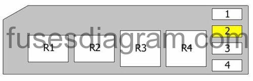
| Fuse | Amps | Circuits protected |
|---|---|---|
| 1 | Not used | |
| 2 | 20 | Engine control unit |
| 3 | Not used | |
| 4 | EGR valve Boost pressure regulator solenoid | |
| R1 | Front fog light relay | |
| R2 | Fuel pump relay Additional relay, fuel pump | |
| R3 | Fuel heater relay | |
| R4 | Main relay |