For the Volkswagen Fox (Lupo) 2005, 2006, 2007, 2008, 2009, 2010, 2011 model year.
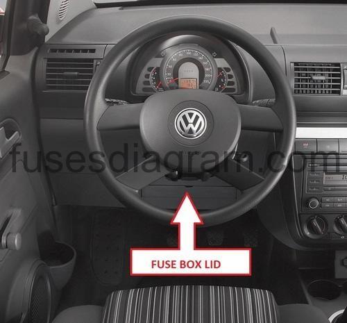
Fuse box in passenger compartment.
fuse box location.
fuse box diagram.
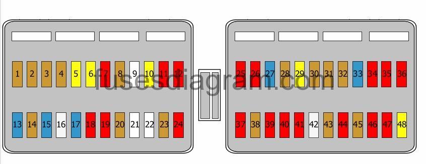
legend.
| Fuse | Amps | Circuits Protected |
|---|---|---|
| 1 | 5A | Cooling fan control unit Air-conditioning control unit |
| 2 | 5A | Comfort system control unit Power supply control unit |
| 3 | 5A | Speed sensor Power steering control unit |
| 4 | 5A | Alarm switch |
| 5 | 20A | Radio |
| 6 | 20A | Heated rear windscreen relay |
| 7 | 10A | Intermittent wiper |
| 8 | 5A | Power supply control unit |
| 9 | Not used | |
| 10 | 20A | Sliding roof control unit |
| 11 | 10A | Comfort system control unit |
| 12 | 10A | Comfort system control unit |
| 13 | 15A | Additional headlights |
| 14 | 5A | Comfort system control unit Mirror switch |
| 15 | 15A | Heated driver’s seat Heated front passenger’s seat |
| 16 | 25A | Comfort system control unit |
| 17 | 15A | Fog light switch Fog light switch illumination |
| 18 | 10A | Rear windscreen wiper |
| 19 | 10A | Automatic transmission control unit |
| 20 | 5A | Heated rear-view mirror |
| 21 | Not used | |
| 22 | Not used | |
| 23 | 5A | ABS control unit |
| 24 | 10A | ABS control unit |
| 25 | 10A | Start signal |
| 26 | 10A | Engine control unit Ignition transformer |
| 27 | 15A | Air-conditioning control unit Diagnostic connector (16) |
| 28 | 5A | Comfort system control unit Dash panel insert |
| 29 | 20A | Automatic intermittent wash/wipe system |
| 30 | 5A | Engine control unit |
| 31 | 5A | Right sidelight |
| 32 | 5A | Number plate light(s) |
| 33 | 15A | Fuel pressure pump |
| 34 | 10A | Cab charcoal filter |
| 35 | 10A | Dash panel insert Left main beam |
| 36 | 10A | Left dipped beam |
| 37 | 10A | Reversing light switch Left reversing light Right reversing lights |
| 38 | 5A | Clutch pedal switch Brake pedal switch Fuel pump relay Dash panel insert |
| 39 | 10A | Luggage compartment light(s) |
| 40 | 10A | Brake light switch |
| 41 | 10A | Horn |
| 42 | 25A | Blower switch |
| 43 | 5A | Left sidelight |
| 44 | 10A | Engine control unit Injectors (cylinders 1 – 4) |
| 45 | 5A | Oxygen sensor Oxygen sensor behind the catalytic converter Clutch pedal switch High-output heating relay Brake pedal switch Low-output heating relay (10A also used) |
| 46 | 10A | Right main beam |
| 47 | 10A | Right dipped beam |
| 48 | 20A | Cigarette lighter 12V socket |
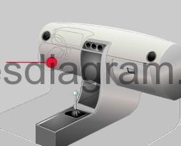
Relay box in passenger compartment.
location.
relay box diagram.
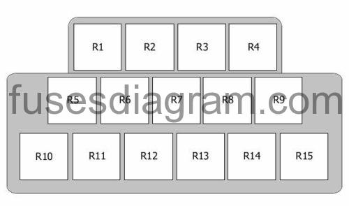
Relay R1 – Not used
Relay R2 – Daylight running system, side and tail lights
Relay R3 – Glow plug relay
Relay R4 – Fuel pump relay/additional relay, fuel pump
Relay R5 – Headlight/Main beam relay
Relay R6 – Not used
Relay R7 – Automatic gearbox
Relay R8 – Low-output heating relay
Relay R9 – High-output heating relay
Relay R10 – Blower/Cooling fan relay
Relay R11 – X contact relief relay
Relay R12 – Fuel supply relay
Relay R13 – Power supply relay
Relay R14 – Not used
Relay R15 – Cooling fan relay, stage 2
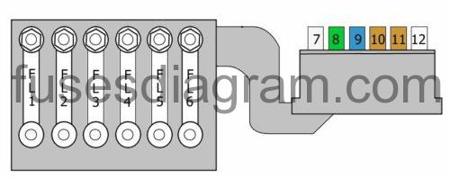
Fuse box in engine compartment (on battery).
| Fuse | Amps | Circuits Protected |
|---|---|---|
| FL1 | 175A | Alternator |
| FL2 | 110A | Terminal 30 |
| FL3 | 50A | Power steering control unit |
| FL4 | 40A | Secondary air pump relay |
| FL5 | 40A | Radiator fan control unit |
| FL6 | 40A | ABS control unit |
| 7 | 25A | ABS control unit |
| 8 | 30A | Air-conditioning control unit |
| 9 | 15A | Engine control unit (30A also used) |
| 10 | 5A | Power supply control unit |
| 11 | 5A | Air-conditioning control unit |
| 12 | Not used |