For the Volkswagen Passat B7 2010, 2011, 2012, 2013, 2014, 2015 model year.
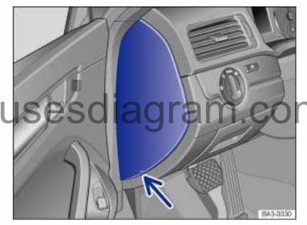
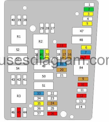
Fuse box in passenger compartment.
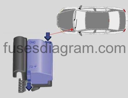
Fuse box location.
On the driver side in the instrument panel.
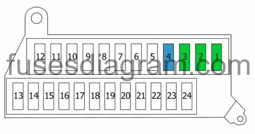
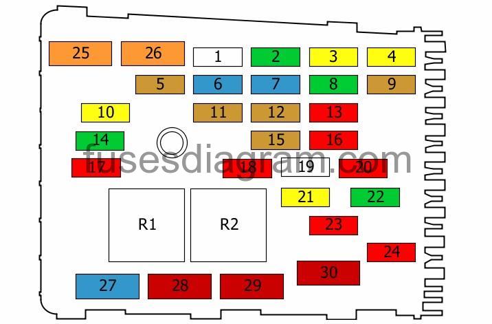
fuse box diagram.
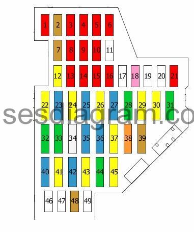
legend.
| Fuse | AMPS | Circuits Protected |
|---|---|---|
| 1 | 10A | Air-conditioning high-pressure sensor Air quality sensor Oil level and temperature sensor Blower relay DC-AC converter with socket, 12V – 230V Automatic anti-dazzle rear-view mirror |
| 2 | 5A | Light switch TCS/ESP button Auto-hold button ABS control unit Power steering control unit Handbrake control unit |
| 3 | 10A | Power supply relay Crankcase breather heater Injectors |
| 4 | 10A | Rear roller blind Engine Start and Stop system switch Damping control unit Adaptive cruise control unit Parking control unit Parking assistance control unit Trailer detection control unit Camera control unit Diagnostic connector |
| 5 | 10A | Headlight range control Left headlight range control motor Right headlight range control motor |
| 6 | 10A | 4WD control unit |
| 7 | 5A | Control panel control unit Data bus diagnostic interface |
| 8 | 10A | Right headlight or not used |
| 9 | 10A | Airbag control unit Passenger’s side airbag deactivation light |
| 10 | 10A | Mass airflow meter Voltage regulator(s) Fuel pump control unit Engine control unit Terminal 50 voltage supply relay Power supply relay Starter relay 1 Starter relay 2 |
| 11 | 25A | Not used |
| 12 | 20A | Comfort system control unit |
| 13 | 10A | Light switch Selector lever ABS control unit Handbrake warning light Diagnostic connector |
| 14 | 10A | Alarm horn Interior monitoring |
| 15 | 10A | Rain and light sensor Heated rear windscreen relay Heated windscreen relay Climatronic control unit Air-conditioning control unit Rear-view camera control unit Engine Start and Stop system control unit Remote control receiver for the auxiliary coolant heater |
| 16 | 10A | Ignition lock Electronic steering column lock Engine Start and Stop system control unit |
| 17 | 25A | Not used |
| 18 | 3A | Power supply control unit Voltage regulator(s) Engine control unit Power supply relay |
| 19 | 25A | Not used |
| 20 | 25A | Not used |
| 21 | 10A | Rear roller blind control unit |
| 22 | 20A | Handbrake control unit |
| 23 | 15A | Trailer detection control unit Or Trailer detection control unit Electronic damper control unit |
| 24 | 20A | Handbrake control unit |
| 25 | 15A | Trailer detection control unit Emergency assistance call switch |
| 26 | 20A | Front interior light Or Front interior light Sliding roof control unit |
| 27 | 15A | Fuel pump control unit Or Fuel pump relay (20A also used) |
| 28 | 30A | Rear passenger’s door control unit Driver’s door control unit |
| 29 | 20A | Control unit, heated rear seats |
| 30 | 20A | Sliding roof control unit |
| 31 | 30A | DC-AC converter with socket, 12V – 230V |
| 32 | 30A | Heated rear windscreen |
| 33 | 30A | Headlight washer relay Headlight washer pump |
| 34 | 25A | Control unit, heated front seats |
| 35 | 15A | Driver’s seat adjustment switch |
| 36 | 15A | Trailer connector socket supply relay |
| 37 | 20A | Trailer detection control unit Or Trailer detection control unit Tailgate |
| 38 | 40A | Blower relay Blower control unit Air-conditioning control unit |
| 39 | 5A | Selector lever Reversing light switch Mechatronic unit for the dual-clutch gearbox |
| 40 | 15A | Power supply control unit Rear wiper motor Front and rear washer pumps |
| 41 | 20A | Power supply control unit Or Power supply control unit Cigarette lighter Rear cigarette lighter |
| 42 | 15A | 12V socket |
| 43 | 20A | Additional heater control unit |
| 44 | 30A | Driver’s door control unit Front passenger’s door control unit |
| 45 | 20A | Additional heater relay |
| 46 | 25A | Not used |
| 47 | 25A | Analogue clock TV tuner |
| 48 | 5A | Control panel control unit |
| 49 | 25A | Not used |
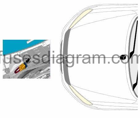
Additional fuse box.
fuse box location.
fuse box layout.
| 1 | Tailgate 30.0 A |
| 2 | Tailgate 30.0 A |
| 3 | Sunroof roller blind control unit 30.0 A |
| 4 | Electronic damper control unit Police equipment 15.0 A |
| 5 | Police equipment |
| 6 | Police equipment |
| 7 | Police equipment |
| 8 | Police equipment |
| 9 | Police equipment |
| 10 | Not used |
| 11 | Not used |
| 12 | Not used |
| 13 | Special vehicles |
| 14 | Special vehicles |
| 15 | Special vehicles |
| 16 | Special vehicles |
| 17 | Special vehicles |
| 18 | Special vehicles |
| 19 | Special vehicles |
| 20 | Special vehicles |
| 21 | Special vehicles |
| 22 | Special vehicles |
| 23 | Special vehicles |
| 24 | Special vehicles |
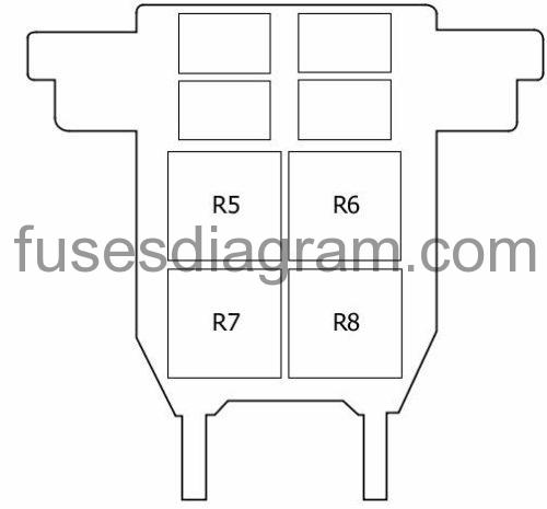
Additional relay.
location.
fuse box diagram.
R1 – Not used
Relay R2 – Not used
Relay R3 – Not used
Relay R4 – Not used
Relay R5 – Not used
Relay R6 – Not used
Relay R7 – Second battery charging circuit relay
Relay R8 – Not used
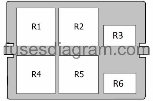
Relay box №1 in passenger compartment Passat B7.
relay box diagram.
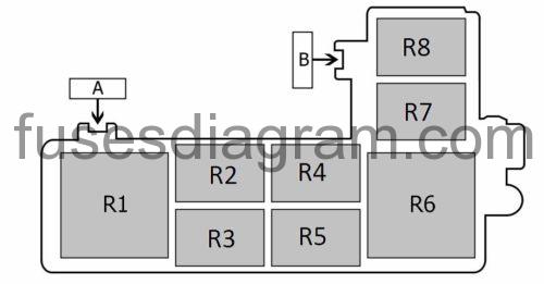
| A | Not used |
| B | (No value is available) Driver’s seat adjustment |
| R1 | Blower relay |
| R2 | Additional heater relay |
| R3 | Additional heater relay or not used |
| R4 | Fuel pump relay or not used |
| R5 | Power supply relay Or Power supply relay Coolant circulation pump |
| R6 | Terminal 50 voltage supply relay or not used |
| R7 | Starter relay 2 or not used |
| R8 | Starter relay 2 or not used |
Relay box №2 in passenger compartment.
Reley box layout.
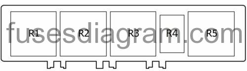
| R1 | Heated rear windscreen relay |
| R2 | Terminal 15 voltage supply relay |
| R3 | Horn relay Headlight washer relay |
| R4 | Trailer connector socket supply relay or not used |
| R5 | X contact relief relay |
Fuse box in engine compartment Volkswagen Passat B7.
fuse box diagram (30 fuses (E-box Low).
legend.
| 1 | Not used | |
| 2 | 30A | ABS control unit |
| 3 | 20A | Horns Horn relay |
| 4 | 20A | Trailer detection control unit |
| 5 | 5A | Power supply control unit Battery monitor control unit |
| 6 | 15A | Mechatronic unit for the dual-clutch gearbox |
| 7 | 15A | Radio Information display control unit Voltage regulator(s) (20A also used) (30A also used) |
| 8 | 30A | Mechatronic unit for the dual-clutch gearbox |
| 9 | 5A | Electronic steering wheel control unit |
| 10 | 20A | Ignition coils Fuel pressure control solenoid Fuel metering solenoid |
| 11 | 5A | Control panel control unit |
| 12 | 5A | TV tuner |
| 13 | 10A | Main relay Terminal 30 voltage supply Engine control unit |
| 14 | 30A | Engine control unit (25A also used) |
| 15 | 5A | Data bus diagnostic interface |
| 16 | 10A | Exhaust gas cooler solenoid Engine coolant circulation pump Boost pressure sensor Or Exhaust gas cooler solenoid Coolant pump Engine coolant circulation pump Magnetic clutch Continued coolant circulation relay |
| 17 | 10A | Fuel pressure control solenoid Fuel tank shut-off valve Coolant circulation pump Low-output heating relay (40A also used) |
| 18 | 10A | High-pressure valve Fuel quality sensor |
| 19 | Not used | |
| 20 | 10A | Brake light switch Clutch pedal position sensor Low-output heating relay High-output heating relay Fuel pressure control solenoid Power supply relay |
| 21 | 20A | Additional heater control unit |
| 22 | 30A | Wiper control unit |
| 23 | 10A | Brake pedal switch Mass airflow meter Clutch pedal switch Fuel pump relay Glow plug control unit Relay, additional coolant pump Turbo pressure control solenoid Canister purge solenoid Camshaft timing solenoid Inlet manifold shut-off valve Oil pressure control solenoid |
| 24 | 10A | Oxygen sensor in front of the catalytic converter Oxygen sensor behind the catalytic converter (15A also used) |
| 25 | 10A | Power supply control unit |
| 26 | 40A | Power supply control unit |
| 27 | 40A | Heated windscreen |
| 28 | 60A | Glow plug control unit |
| 29 | 50A | Power supply control unit X contact relief relay |
| 30 | 50A | Power supply control unit Terminal 15 voltage supply relay |
| R1 | 50A | Power supply relay |
| R2 | Terminal 30 voltage supply relay Or Terminal 30 voltage supply relay Main relay |
fuse box diagram (54 fuses (E-box High).
| 1 | Not used | |
| 2 | 30A | ABS control unit |
| 3 | 20A | Trailer detection control unit |
| 4 | Not used | |
| 5 | 20A | Horns Horn relay |
| 6 | 20A | Ignition coils |
| 7 | 15A | Fuel pressure control solenoid |
| 8 | 10A | Brake pedal switch Continued coolant circulation relay Radiator fan control unit Canister purge solenoid Inlet camshaft timing solenoid Outlet camshaft timing solenoid |
| 9 | 5A | Circulation pump relay |
| 10 | 10A | Main relay |
| 11 | 25A | Engine control unit |
| 12 | 10A | Analogue clock |
| 13 | Not used | |
| 14 | Not used | |
| 15 | 10A | Engine coolant circulation pump |
| 16 | 5A | Electronic steering wheel control unit |
| 17 | 5A | Control panel control unit |
| 18 | Not used | |
| 19 | 15A | Radio Navigation control unit Information display |
| 20 | 5A | Analogue clock TV tuner |
| 21 | Not used | |
| 22 | Not used | |
| 23 | Not used | |
| 24 | 5A | Data bus diagnostic interface |
| 25 | Not used | |
| 26 | 10A | Main relay Engine control unit |
| 27 | Not used | |
| 28 | Not used | |
| 29 | Not used | |
| 30 | 20A | Additional heater control unit |
| 31 | 30A | Wiper control unit |
| 32 | Not used | |
| 33 | 15A | Oxygen sensor in front of the catalytic converter Oxygen sensor behind the catalytic converter |
| 34 | Not used | |
| 35 | 20A | Additional heater relay |
| 36 | Not used | |
| 37 | Not used | |
| 38 | Not used | |
| 39 | Not used | |
| 40 | Not used | |
| 41 | Not used | |
| 42 | Not used | |
| 43 | Not used | |
| 44 | Not used | |
| 45 | 10A | Oxygen sensor in front of the catalytic converter Oxygen sensor behind the catalytic converter |
| 46 | Not used | |
| 47 | 40A | Power supply control unit |
| 48 | 40A | Power supply control unit |
| 49 | 50A | Terminal 15 voltage supply relay |
| 50 | Not used | |
| 51 | Not used | |
| 52 | 60A | Heated windscreen |
| 53 | 50A | X contact relief relay |
| 54 | Not used | |
| R1 | No information is available | |
| R2 | Continued coolant circulation relay | |
| R3 | Not used | |
| R4 | Main relay |
Fuse box in engine compartment (E-box Low).
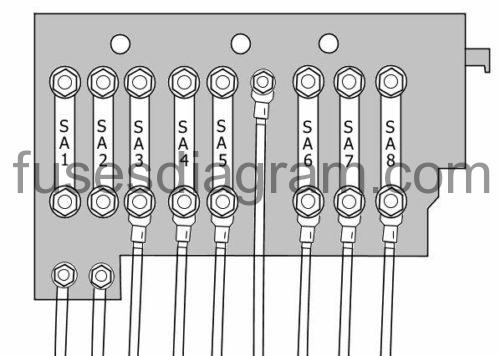
| SA1 | 180A | Alternator (150A also used) |
| SA2 | 80A | Electromechanical power steering motor |
| SA3 | 50A | Radiator fan control unit |
| SA4 | 60A | Fuse and relay box in passenger compartment, fuses 12 – 17 Fuse and relay box in passenger compartment, fuses 22, 27, 28, 44 |
| SA5 | 60A | Fuse and relay box in passenger compartment, fuses 29 – 31 |
| SA6 | 60A | Fuse and relay box in passenger compartment, fuses 32, 33 |
| SA7 | 60A | Second battery charging circuit relay |
| SA8 | 40A | ABS control unit |
Fuse box in engine compartment (E-box High).
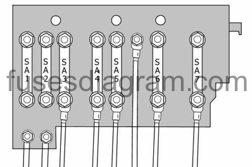
| SA1 | 180A | Alternator (150A also used) |
| SA2 | 80A | Electromechanical power steering motor |
| SA3 | 50A | Radiator fan control unit |
| SA4 | 60A | Fuse and relay box in passenger compartment, fuses 27, 29 |
| SA5 | 60A | Fuse and relay box in passenger compartment, fuses 12 – 17 Fuse and relay box in passenger compartment, fuses 32 – 37 Or Fuse and relay box in passenger compartment, fuses 12 – 17 |
| SA6 | 60A | Fuse and relay box in passenger compartment, fuses 32 – 37 or not used |
| SA7 | 40A | ABS control unit |
Relay box in engine compartment (under fuse box).
Relay R1 – Starter relay 1
Relay R2 – Glow plug relay
Relay R3 – Not used
Relay R4 – Low-output heating relay
Relay R5 – High-output heating relay
Relay R6 – Starter relay 2
Heated windscreen relay.