For the Audi A8 (D4) (4H) 2010, 2011, 2012, 2013, 2014, 2015, 2016, 2017 model year.
| Cigarette lighter fuse – (fuse box in luggage compartment, fuse №47/20A and №48/20A) |
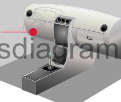
Fuse box in passenger compartment.
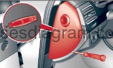
fuse box location.
Driver side of the cockpit: fuse panel cover.
fuse box diagram.
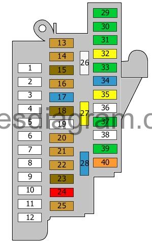
legend.
| Fuse | Amps | Circuits protected |
|---|---|---|
| 13 | 5A | Lighting switch |
| 14 | 5A | Entry and start authorisation switch |
| 15 | 7,5A | Door control unit, rear left or not used |
| 16 | 5A | Head-up display control unit |
| 17 | 15A | Horn relay Horns |
| 18 | 7,5A | Control unit, roof electronics |
| 19 | Not used | |
| 20 | 5A | Control unit, steering column electronics (10A also used) |
| 21 | 5A | Controller area network (CAN) or not used |
| 22 | 5A | Steering column lock control unit |
| 23 | 7,5A | Driver’s door control unit or not used |
| 24 | 10A | Rain and light sensor Diagnostic connector (16) |
| 25 | 5A | Additional heater remote control receiver |
| 26 | 25A | Steering column adjustment control unit Steering column adjustment, vertical Steering column adjustment, horizontal |
| 27 | 20A | Power supply control unit |
| 28 | 15A | Brake servo relay Brake vacuum pump |
| 29 | 30A | Power supply control unit |
| 30 | 30A | Wiper control unit |
| 31 | 30A | Power supply control unit |
| 32 | 20A | Sunroof control unit Sunroof motor |
| 33 | 30A | Driver’s door control unit Driver’s side power window |
| 34 | 15A | Passenger’s seat control unit (7.5A also used) |
| 35 | 20A | Sunroof control unit Sunroof motor |
| 36 | 35A | Active steering control unit |
| 37 | 30A | Power supply control unit |
| 38 | 35A | Power supply control unit |
| 39 | 30A | Door control unit, rear left Rear left power window |
| 40 | 40A | Sunroof roller blind control unit Sunroof roller blind |
Front passenger side cockpit: fuse panel with plastic bracket.
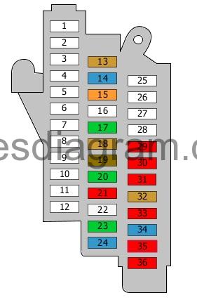
legend.
| Fuse | Amps | Circuits protected |
|---|---|---|
| 13 | 5A | Alarm sensor Alarm horn |
| 14 | 15A | Automatic transmission control unit |
| 15 | 40A | Fresh-air blower control unit |
| 16 | 35A | Motronic power supply relay Terminal 30 voltage supply relay Power supply relay |
| 17 | 30A | Additional heater control unit |
| 18 | 5A | Engine control unit Engine control unit 2 |
| 19 | 7,5A | Front passenger’s door control unit or not used |
| 20 | 30A | Front passenger’s door control unit Front passenger’s power window |
| 21 | 10A | ABS control unit |
| 22 | 25A | ABS control unit |
| 23 | 30A | Door control unit, rear right Rear right power window |
| 24 | 15A | Passenger’s seat control unit (7.5A also used) |
| 25 | Not used | |
| 26 | Not used | |
| 27 | Not used | |
| 28 | Not used | |
| 29 | 10A | Special equipment (15A also used) |
| 30 | 10A | Special equipment (15A also used) |
| 31 | 10A | Special equipment |
| 32 | 5A | Special equipment (15A also used) |
| 33 | 10A | Special equipment |
| 34 | 15A | Special equipment |
| 35 | 10A | Special equipment |
| 36 | 10A | Special equipment |
Fuse and relay box in passenger compartment.
fuse and relaybox diagram.
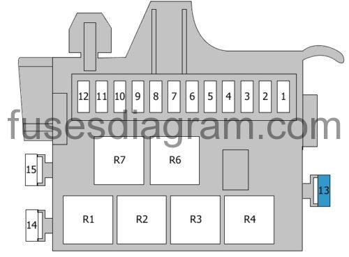
Fuse 13 (15.0 A) – Driver’s seat adjustment
Relay R6 – Horn relay or Brake servo relay or not used
Relay R7 – Emergency off relay or not used
Fuse box in luggage compartment.
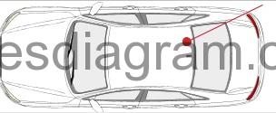
fuse box diagram.
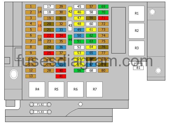
legend.
| Fuse | Amps | Circuits protected |
|---|---|---|
| 1 | 5A | TCS/ESP button Headlight range control unit Power supply control unit Diagnostic connector (16) |
| 2 | 5A | Data bus diagnostic interface |
| 3 | 5A | Adaptive suspension control unit |
| 4 | 5A | Parking assistance control unit |
| 5 | 5A | Control unit, steering column electronics |
| 6 | 5A | Control unit |
| 7 | 5A | Airbag control unit Passenger’s side airbag deactivation light Seat occupied recognition control unit |
| 8 | 5A | Garage door operation control unit Night vision system control unit Control unit for the air quality improvement system Heated washer jets 4WD control unit |
| 9 | 5A | Handbrake control unit |
| 10 | 5A | Auto-hold button Trailer detection control unit Cooler box Heated seat control unit Automatic anti-dazzle rear-view mirror |
| 11 | 5A | Active steering control unit |
| 12 | 5A | Selector lever control unit |
| 13 | 5A | Lane change assist control unit |
| 14 | 5A | Engine control unit |
| 15 | 40A | Starter motor relay Starter motor, secondary relay |
| 16 | 5A | Headlight range control unit Power output control unit for the left headlight (10A also used) |
| 17 | 25A | Seat belt pretensioner control unit |
| 18 | 25A | Seat belt pretensioner control unit |
| 19 | 5A | Engine control unit or not used |
| 20 | 7,5A | Voltage regulator(s) |
| 21 | 7,5A | Camera control unit |
| 22 | 10A | Power output control unit for the right headlight |
| 23 | 5A | ABS control unit Or ABS control unit Air-conditioning compressor |
| 24 | 7,5A | Crankcase breather heater Emergency off relay Or Voltage regulator(s) Engine mount control unit Control unit for sound transmitted through the vehicle body structure or not used |
| 25 | 10A | Adaptive cruise control unit Or Adaptive cruise control unit Battery |
| 26 | 5A | Automatic transmission control unit Or Automatic transmission control unit Controller area network (CAN) |
| 27 | 5A | Air quality sensor Refrigerant pressure and temperature sensor Humidity sender |
| 28 | 5A | Special equipment |
| 29 | 5A | Electric parking brake |
| 30 | 5A | Control unit |
| 31 | 7,5A | Door control unit, rear right or not used |
| 32 | 5A | Fuel tank leakage control unit Fuel tank pressure sensor Telephone or not used |
| 33 | 15A | Climatronic control unit |
| 34 | 10A | Air-conditioning control unit |
| 35 | 5A | Data bus diagnostic interface |
| 36 | 15A | Cooler box |
| 37 | 5A | Connector |
| 38 | 5A | Telephone Aerial selection control unit Chip card reader or not used |
| 39 | 15A | Engine mount control unit |
| 40 | 10A | Selector lever control unit |
| 41 | 10A | Comfort system control unit |
| 42 | 20A | Comfort system control unit |
| 43 | 25A | Fuel pump control unit Fuel pump relay |
| 44 | 30A | Handbrake control unit |
| 45 | Not used | |
| 46 | 20A | 12V socket |
| 47 | 20A | Rear cigarette lighter Additional 12V sockets |
| 48 | 20A | Cigarette lighter DC-AC converter with socket, 12V – 230V |
| 49 | 15A | Adaptive suspension control unit |
| 50 | 15A | DC-AC converter with socket, 12V – 230V |
| 51 | 30A | Handbrake control unit |
| 52 | 25A | Heated seat control unit Air-conditioning control unit Heated rear seat(s) switch |
| 53 | 20A | Comfort system control unit |
| 54 | 20A | Fresh-air blower control unit Blower |
| 55 | 20A | Comfort system control unit |
| 56 | 30A | Control unit |
| 57 | 5A | Rear seat adjustment Remote control for seat operation |
| 58 | 35A | Cooling fan relay or not used |
| 59 | 7,5A | Seat adjustment |
| 60 | 25A | Trailer detection control unit Trailer connector socket (30A also used) |
| 61 | 20A | Trailer detection control unit Trailer connector socket (25A also used) |
| 62 | 30A | Seat adjustment |
| 63 | 30A | Seat adjustment |
| 64 | 20A | Trailer detection control unit Trailer connector socket (25A also used) |
| 65 | 15A | Trailer detection control unit Trailer connector socket |
| 66 | 7,5A | Seat adjustment |
| 67 | 15A | Battery or not used |
| 68 | Not used | |
| 69 | 30A | Digital sound package control unit Voltage regulator(s) Radio |
| 70 | 30A | Digital sound package control unit |
| 71 | 10A | Multimedia control unit Voltage regulator(s) Information display control unit Information display |
| 72 | 5A | Tyre pressure monitor control unit or not used |
| 73 | 5A | Rear-view camera control unit Automatic anti-dazzle rear-view mirror or not used |
| 74 | 5A | DVD |
| 75 | 5A | TV tuner |
| 76 | 7,5A | Information display control unit Multimedia control unit |
| 77 | 5A | Control panel control unit Analogue clock |
| 78 | 5A | Vehicle information control unit |
| 79 | 7,5A | Radio |
| 80 | 5A | Telephone Aerial selection control unit Chip card reader Rear-view camera control unit or not used |
| 81 | Not used | |
| 82 | 80A | (110A also used) No information is available |
| 83 | 110A | No information is available |
| 84 | 40A | Heated rear windscreen |
| 85 | 40A | Levelling system |
| 86 | 40A | Engine Start and Stop system switch |
| 87 | 15A | Front passenger’s seat adjustment |
| R1 | Adaptive suspension compressor relay | |
| R2 | Heated rear windscreen relay | |
| R3 | Automatic anti-dazzle rear-view mirror Or Automatic anti-dazzle rear-view mirror Cooling fan relay | |
| R4 | Fuel pump relay | |
| R5 | Starter motor relay Starter motor, secondary relay | |
| R6 | Terminal 15 voltage supply relay | |
| R7 | Power socket relay |
Main fuse box in luggage compartment.
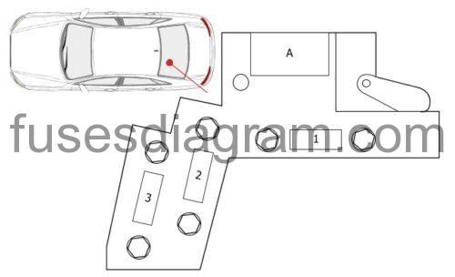
Fuse 1 (175.0 A) – Main fuse
Fuse 2 (110.0 A) – Main fuse
Fuse 3 (40.0 A) – Main fuse (80A also used) (150A also used)
A – Battery isolation/igniter
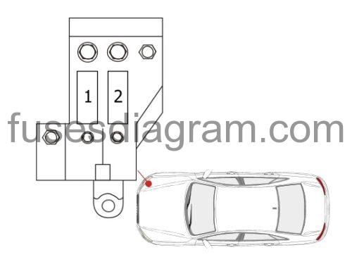
Main fuse box in luggage compartment.
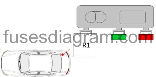
Fuse 1 (30.0 A) – Reductant heater
Fuse 2 (10.0 A) -Reductant metering system
Relay R1 – Reductant metering system relay
Fuse box in engine compartment.
fuse box diagram.
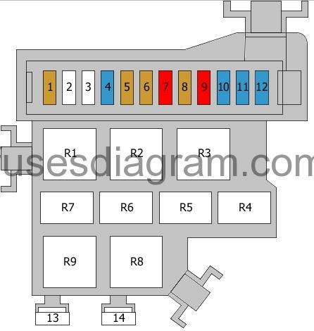
legend.
| Fuse | Amps | Circuits protected |
|---|---|---|
| 1 | 5A | Mass airflow meter Mass airflow meter 2 |
| 2 | Not used | |
| 3 | Not used | |
| 4 | 15A | Engine control unit Engine control unit 2 |
| 5 | 5A | Cooling fan control unit Cooling fan control unit 2 Fuel pump control unit Cooling fan Cooling fan 2 Fuel pump relay |
| 6 | 5A | Brake light switch |
| 7 | 10A | Glow plug control unit Left electro-hydraulic engine mounting solenoid Gearbox mounting solenoids Gearbox oil cooling valve |
| 8 | 5A | Oil level and temperature sensor |
| 9 | 10A | Gearbox mounting solenoids Fuel pressure control solenoid Fuel metering solenoid |
| 10 | 15A | Oxygen sensors |
| 11 | 15A | Glow plug control unit Right electro-hydraulic engine mounting solenoid Exhaust gas cooler solenoid Oil pressure control valve Coolant system bypass circuit valve Connector Gearbox mounting solenoids |
| 12 | 15A | Exhaust gas recirculation coolant pump Coolant circulation pump Or Exhaust gas recirculation coolant pump |
| 13 | 80A | Glow plug |
| 14 | 50A | Glow plug or not used |
| R1 | Not used | |
| R2 | Not used | |
| R3 | Not used | |
| R4 | No information is available | |
| R5 | No information is available | |
| R6 | No information is available | |
| R7 | No information is available | |
| R8 | Glow plug control unit | |
| R9 | Glow plug control unit or not used |
Additional fuses in engine compartment.
Fuse 1 (40.0 A) – Cooling fan
(60A also used)
Fuse 2 (40.0 A) – Cooling fan
(60A also used)