The cars considered are Audi A4 B7 (8E, 8H) 2004, 2005, 2006, 2007, 2008, 2009. Gasoline, Diesel (1.6, 1.8, 2.0, 2.5, 2.7, 3.0, 3.2). Restyling, pre-restyling. You will also know where the fuses are located, specifically the fuel pump fuse, cigarette lighter fuses, heater fuses, etc.
| Cigarette lighter fuse – (fuse box in passenger compartment, fuse №33/15A). |
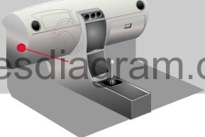
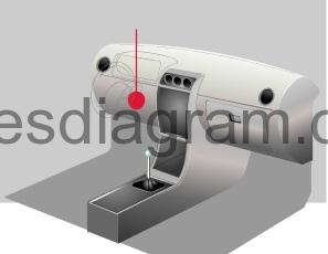
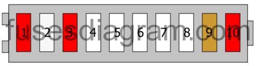
Fuse box laout Audi A4 B7.
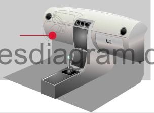
Passenger compartment.
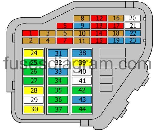
legend.
| Fuse | Amps | Circuits protected |
|---|---|---|
| 1 | 10A | Air-conditioning control unit. Climatronic. |
| 2 | 5A | Footwell light(s). |
| 3 | 5A | Heated washer jets. |
| 4 | 5A | Cooling fan control unit. |
| 5 | 10A | Rear roller blind. Multifunction switch. Oil level sensor. Oil temperature sensor. Navigation system. Parking assistance control unit. |
| 6 | 5A | Air quality sensor. Climatronic. Heated front seat(s). Air-conditioning high-pressure sensor. TCS/ESP button. |
| 7 | 10A | Traction control switch. Clutch switch. ABS control unit. Brake pedal switch. |
| 8 | 5A | Telephone. Telephone amplifier. |
| 9 | 15A | Brake servo relay. |
| 10 | 5A | Headlight range control. |
| 11 | 5A | Airbag control unit. Airbag warning light. |
| 12 | 10A | Diagnostic connector. |
| 13 | 10A | Control unit, steering column electronics. |
| 14 | 10A | Brake light switch. |
| 15 | 10A | Control unit with display in the dash panel insert. Navigation system. CD player. |
| 16 | 5A | Garage door opener. |
| 17 | 10A | Rain sensor. Daylight running system. Parking assistance control unit. |
| 18 | 5A | |
| 19 | 15A | Fog light(s). |
| 20 | Not used | |
| 21 | Not used | |
| 22 | 15A | Door control unit, front left. Door control unit, front right. |
| 23 | 15A | Door control unit, rear left. Door control unit, rear right. |
| 24 | 20A | Comfort system electrics. |
| 25 | 30A | Blower. Air conditioning. |
| 26 | 30A | Heated rear windscreen. |
| 27 | 30A | Trailer detection control unit. |
| 28 | 20A | Fuel pump. |
| 29 | Not used | |
| 30 | 20A | Sliding roof control unit. |
| 31 | 15A | Reversing light switch. Mass airflow meter. Automatic transmission control unit. Light sensor. Starter relay. Selector handle lock solenoid. Diagnostic connector. Automatic anti-dazzle rear-view mirror. |
| 32 | Not used | |
| 33 | 15A | Cigarette lighter. |
| 34 | 30A | 12V socket. |
| 35 | 30A | Accessory socket. |
| 36 | 30A | Power supply control unit. Rear wiper motor. |
| 37 | 30A | Power supply control unit. Headlight washer pump. |
| 38 | 15A | Alarm horn. Comfort system electrics. Interior monitoring. |
| 39 | 20A | Radio. Audio amplifier. |
| 40 | 25A | Horn. |
| 41 | Additional heater control unit. Remote control receiver. | |
| 42 | 30A | ABS control unit. |
| 43 | 15A | Mass airflow meter. Engine management. EGR. Main relay. Engine control unit. Engine control unit relay. |
| 44 | 30A | Climate control unit. |
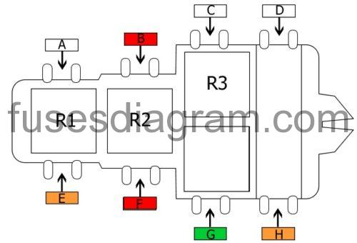
Fuse and relay box №1.

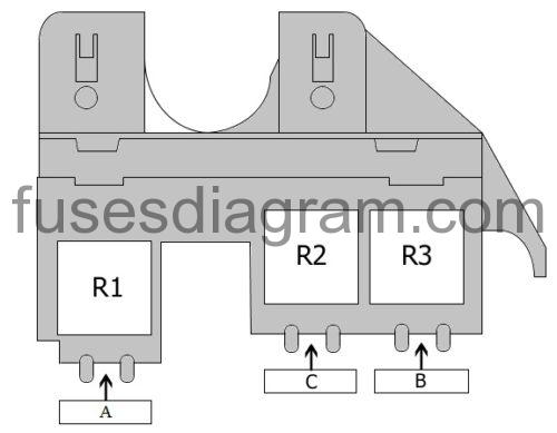
legend.
| Fuse | Amps | Circuits protected |
|---|---|---|
| A | Not used | |
| B | 40A | Additional heater. |
| C | 60A | Additional heater. |
| R1 | Special vehicles. | |
| R2 | Low-output heating relay. | |
| R3 | High-output heating relay. |
Fuse and relay box №2 in passenger compartment.
fuse box diagram.
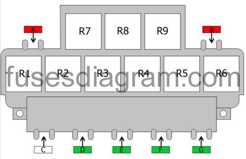
legend.
| Fuse | Amps | Circuits protected |
|---|---|---|
| A | 10A | Rear roller blind. |
| B1 | 10A | 12V socket. |
| B2 | 10A | Rear roller blind. |
| C | not used | |
| D | 30A | Window regulator. |
| E1 | 30A | Driver’s seat adjustment. |
| E2 | 10A | Driver’s seat adjustment. |
| F | 30A | Window regulator. |
| G | 30A | Trailer towing module. |
| R1 | Fuel pump relay. Additional relay, fuel pump. | |
| R2 | Servotronic control unit. | |
| R3 | Starter motor relay. | |
| R4 | Starter motor relay. Brake servo relay. | |
| R5 | Heated rear windscreen relay. | |
| R6 | X contact relief relay. | |
| R7 | Not used. | |
| R8 | Horn relay. | |
| R9 | Not used. |
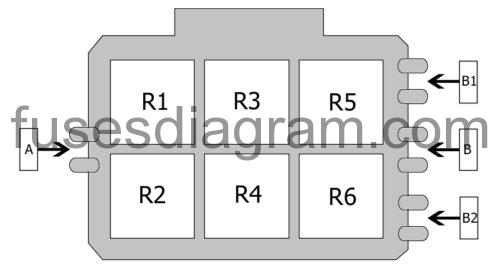
Fuse and relay box №3 in passenger compartment.
fuse box diagram.
legend.
| Fuse | Amps | Circuits protected |
|---|---|---|
| A | Not used | |
| B | 10A | Vermin repellent system. |
| C | Not used | |
| D | Not used | |
| E | 40A | Special vehicles. |
| F1 | 10A | Special vehicles. |
| F2 | 40A | Cooling fan (60A also used). |
| G | 30A | Cooling fan (40A and 60A also used). |
| H | 40A | ABS control unit. |
| R1 | Not used. | |
| R2 | Not used. | |
| R3 | Special vehicles. | |
| R4A | Special vehicles.. | |
| R4B | Taxi package. |
Relay box in passenger compartment.
relay box diagram.
legend.
| Fuse | Amps | Circuits protected |
|---|---|---|
| A | Not used | |
| B | Not used | |
| B1 | Not used | |
| B2 | Not used | |
| R1 | Alarm system. Main beam. Or Main beam relay. | |
| R2 | Special vehicles. Or Taxi package. | |
| R3 | Alarm system control unit. Or Siren relay. | |
| R4 | Alarm system control unit. Or Siren relay. | |
| R5 | Alarm relay. Right direction indicator. Or Flasher relay. | |
| R6 | Alarm relay. Left direction indicator. Or Not used. |
Fuse box №2 in passenger compartment.
fuse box diagram.
legend.
| Fuse | Amps | Circuits protected |
|---|---|---|
| 1 | 10A | Special vehicles. Or Taxi package. |
| 2 | 25A | Special vehicles. Or Alarm system. |
| 3 | 10A | Special vehicles. Or Taxi package. |
| 4 | Special vehicles. | |
| 5 | Special vehicles. | |
| 6 | Special vehicles. | |
| 7 | Special vehicles. | |
| 8 | Special vehicles. | |
| 9 | 5A | Special vehicles. Or Radio. |
| 10 | 10A | Special vehicles. Or 12V socket. |
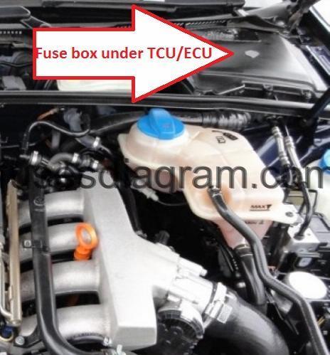
Engine compartment Audi A4 (B7).
fuse box location.
fuse box diagram.
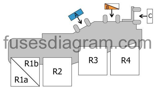
legend.
| Fuse | Amps | Circuits protected |
|---|---|---|
| A | 15A | Engine electronics. |
| B1 | Not used | |
| B2 | 40A | Secondary air injection pump. |
| C | Not used | |
| D | 20A | Engine control unit. |
| E | 15A | Injectors. |
| F | Not used | |
| G | 15A | Engine electronics. |
| R1a | Not used. | |
| R1b | Not used. | |
| R2 | Main relay. | |
| R3 | Secondary air pump relay. | |
| R4 | Not used. |