For the Audi A1 (8X) 2010, 2011, 2012, 2013, 2014, 2015, 2016, 2017, 2018 model year.
| Cigarette lighter fuse – (fuse box in passenger compartment, fuse №3/20A) |
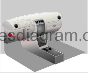
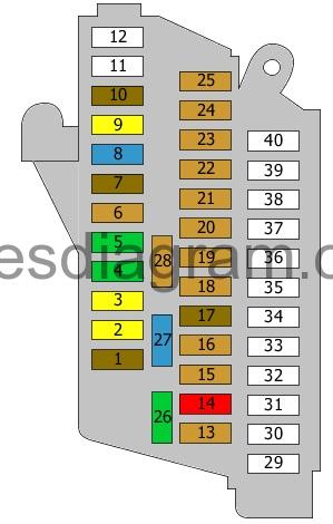
Fuse box in passenger compartment.
fuse box №1 location.
fuse box diagram.
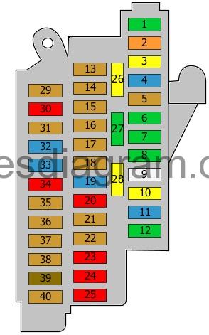
legend.
| Fuse | Amps | Circuits protected |
|---|---|---|
| 1 | 30A | Digital sound package control unit Voltage regulator(s) Radio |
| 2 | 40A | Heater control unit X contact relief relay Fresh-air blower control unit Blower |
| 3 | 20A | Cigarette lighter 12V socket |
| 4 | 15A | Trailer detection control unit |
| 5 | 5A | Data bus diagnostic interface |
| 6 | 30A | Front passenger’s door control unit Door control unit, rear right |
| 7 | 30A | Driver’s door control unit Door control unit, rear left |
| 8 | 30A | Heated rear windscreen Heated rear windscreen relay |
| 9 | 25A | ABS control unit |
| 10 | 20A | Power supply control unit |
| 11 | 15A | Horns Horn relay |
| 12 | 30A | Power supply control unit |
| 13 | 5A | Alarm sensor Alarm horn |
| 14 | 5A | Motronic power supply relay Engine control unit (7.5A also used) Or Terminal 30 voltage supply relay Engine control unit (7.5A also used) |
| 15 | 5A | Power supply control unit |
| 16 | 5A | ABS control unit Voltage regulator(s) |
| 17 | 5A | Radiator fan control unit |
| 18 | 5A | Rain and light sensor Aerial selection control unit Sunroof module |
| 19 | 20A | Fuel pump control unit Or Fuel pump relay (20A also used) |
| 20 | 10A | Relay, additional coolant pump |
| 21 | 5A | Control unit, steering column electronics |
| 22 | 5A | Lighting switch 5.0 A |
| 23 | 10A | Climatronic control unit Air-conditioning control unit Front passenger’s door control unit Door control unit, rear right Diagnostic connector (16) |
| 24 | 10A | Driver’s door control unit Door control unit, rear left |
| 25 | 10A | Power supply control unit |
| 26 | 20A | Radiator fan control unit |
| 27 | 30A | Power supply control unit |
| 28 | 20A | Wiper relay |
| 29 | 5A | Glow plug control unit Brake vacuum pump (20A also used) |
| 30 | 10A | Relay, additional coolant pump Brake light switch Brake pedal switch Heated oxygen sensor Oxygen sensor behind the catalytic converter Or Relay, additional coolant pump Fuse and relay box in passenger compartment, fuses 7, 8 |
| 31 | 5A | Fuel pump relay Fuel pressure control solenoid Coolant circulation pump (7.5A also used) (15A also used) |
| 32 | 15A | Engine control unit Clutch pedal position sensor Brake light switch (30A also used) |
| 33 | 15A | Ignition coils Ignition transformer Fuel pressure control solenoid Fuel metering solenoid (20A also used) (30A also used) |
| 34 | 10A | Radiator fan control unit Turbo pressure control solenoid Canister purge solenoid Camshaft timing solenoid Turbo bypass solenoid Swirl control solenoid EGR cooler change-over valve Oil pressure control valve (15A also used) |
| 35 | 5A | CD changer |
| 36 | 5A | Radio TV tuner Telephone Chip card reader |
| 37 | 5A | Control unit with display in the dash panel insert |
| 38 | 5A | Automatic anti-dazzle rear-view mirror |
| 39 | 7,5A | Radio Information display control unit (15A also used) |
| 40 | 5A | Information display control unit |
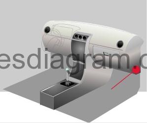
Fuse box №2 in passenger compartment Audi A1.
fuse box diagram.
legend.
| Fuse | Amps | Circuits protected |
|---|---|---|
| 1 | 7,5A | Electronic steering column lock control unit |
| 2 | 20A | Trailer detection control unit |
| 3 | 20A | Trailer detection control unit |
| 4 | 30A | Mechatronic unit for the dual-clutch gearbox |
| 5 | 30A | Headlight washer relay Headlight washer pump |
| 6 | 5A | GPS system |
| 7 | 7,5A | Entry and start authorisation control unit |
| 8 | 15A | Mechatronic unit for the dual-clutch gearbox |
| 9 | 20A | Sliding roof |
| 10 | 7,5A | Gear selector control unit |
| 11 | Not used | |
| 12 | Not used | |
| 13 | 5A | Reversing light switch Gear selector control unit Mechatronic unit for the dual-clutch gearbox |
| 14 | 10A | Air-conditioning high-pressure sensor Oil level and temperature sensor Air-conditioning control unit Power socket relay Automatic anti-dazzle rear-view mirror Diagnostic connector (16) |
| 15 | 5A | Data bus diagnostic interface |
| 16 | 5A | Heater control unit Control unit for sound transmitted through the vehicle body structure |
| 17 | 7,5A | Lighting switch Starter relay 1 Voltage regulator(s) Starter relay 2 Automatic anti-dazzle rear-view mirror Headlights |
| 18 | 5A | Lighting switch |
| 19 | 5A | ABS control unit Voltage regulator(s) |
| 20 | 5A | Front heated seats, controls Hazard warning light switch Heated rear windscreen switch TCS/ESP button Parking switch Tyre pressure monitor switch Engine start/stop switch Trailer detection control unit Heated washer jets |
| 21 | 5A | Power steering control unit |
| 22 | 5A | Mass airflow meter Fuel pump control unit Crankcase breather heater (7.5A also used) |
| 23 | 5A | Airbag control unit Passenger’s side airbag deactivation light |
| 24 | 5A | Parking assistance control unit |
| 25 | 5A | Headlight range control unit |
| 26 | 30A | Heated seat control unit |
| 27 | 15A | Windscreen wiper motor |
| 28 | 5A | Engine control unit |
| 29-40 | not used |
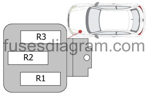
Fuse and relay box in passenger compartment Audi A1.
Fuse box location.
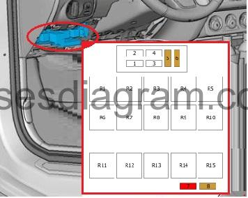
fuse box diagram.
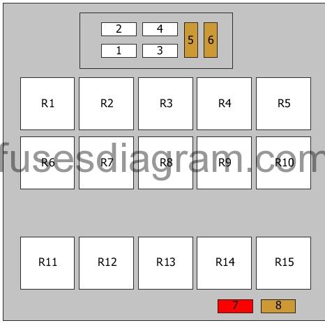
legend.
| Fuse | Amps | Circuits protected |
|---|---|---|
| 1 | 40A | Voltage regulator(s) |
| 2 | 50A | Fuse box No. 2 in passenger compartment, fuses 1 – 12 |
| 3 | 40A | Terminal 15 voltage supply relay |
| 4 | 40A | ABS control unit |
| 5 | 5A | Voltage regulator(s) |
| 6 | 5A | Power supply control unit Voltage regulator(s) Engine control unit |
| 7 | 10A | Brake light switch Clutch pedal position sensor or not used |
| 8 | 5A | Oxygen sensor in front of the catalytic converter Oxygen sensor behind the catalytic converter or not used |
| R1 | Headlight washer relay Horn relay | |
| R2 | Terminal 15 voltage supply relay | |
| R3 | X contact relief relay | |
| R4 | Fuel pump relay Heater relay | |
| R5 | High-output heating relay | |
| R6 | Starter relay 1 Starter relay 2 | |
| R7 | Heated rear windscreen relay | |
| R8 | Motronic power supply relay Power socket relay Or Terminal 30 voltage supply relay Power socket relay | |
| R9 | Low-output heating relay | |
| R10 | Power socket relay Motronic power supply relay Or Power socket relay Terminal 30 voltage supply relay | |
| R11 | Automatic anti-dazzle rear-view mirror or not used | |
| R12 | Not used | |
| R13 | Voltage regulator(s) | |
| R14 | Not used | |
| R15 | Automatic anti-dazzle rear-view mirror or not used |
Fuse box in engine compartment Audi A1.
Fuse box location.
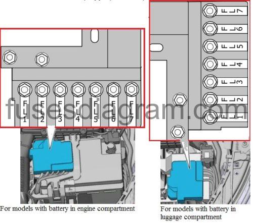
legend.
| Fuse | Amps | Circuits protected |
|---|---|---|
| FL1 | 175A | Alternator |
| FL2 | 40A | Low-output heating relay Additional air heater |
| FL3 | 110A | Power supply or not used |
| FL4 | 80A | Power steering control unit |
| FL5 | 50A | Radiator fan control unit Thermostat (40A also used) |
| FL6 | 50A | Glow plug control unit |
| FL7 | 60A | High-output heating relay Battery monitor control unit Additional air heater |
Relay box in engine compartment.
Relay R1 – Relay, additional coolant pump
Relay R2 – Wiper relay No. 1
Relay R3 – Wiper relay No. 2
Fuse box in luggage compartment on the battery.
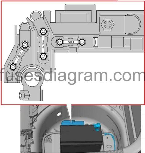
Fuse SD1 – Not used
Fuse SD2 – Power supply (110.0 A)
Fuse SD3 – Not used
Electrical component.
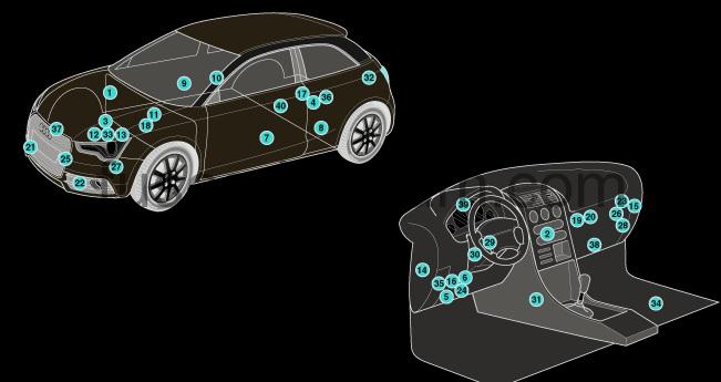
| 1 | ABS control module |
| 2 | AC control module |
| 3 | Battery – Diesel |
| 4 | Battery – petrol- in luggage compartment |
| 5 | Data link connector (DLC) |
| 6 | Diagnostic module |
| 7 | Door function control module, driver |
| 8 | Door function control module, left rear |
| 9 | Door function control module, passenger |
| 10 | Door function control module, right rear |
| 11 | Engine control module (ECM) |
| 12 | Fuse box/relay plate , engine bay1 |
| 13 | Fuse box/relay plate , engine bay 2 |
| 14 | Fuse box/relay plate, fascia 1 |
| 15 | Fuse box/relay plate, fascia 2 |
| 16 | Fuse box/relay plate, fascia 3 |
| 17 | Fuse box/relay plate ,load area-petrol |
| 18 | Glow plug control module |
| 19 | Headlamp level control module |
| 20 | Heater blower speed resistor – in heater box |
| 21 | Horn 1 |
| 22 | Horn 2 |
| 23 | Keyless entry/start control module |
| 24 | Multifunction control module |
| 25 | Outside air temperature sensor |
| 26 | Parking aid control module |
| 27 | Power steering control module |
| 28 | Seat heater control module |
| 29 | Steering column function control module – on steering column |
| 30 | Steering column lock control module – on steering column |
| 31 | Supplementary restraint system (SRS) control module |
| 32 | Trailer control module – LH luggage compartment |
| 33 | Transmission control module (TCM) – on transmission |
| 34 | Voltage stabiliser module 1 – under carpet |
| 35 | Voltage stabiliser module 2- in fascia fuse box/relay plate 3 |
| 36 | Battery control module – petrol – in luggage compartment |
| 37 | Engine coolant blower motor control module |
| 38 | AC/heater blower control module |
| 39 | Instrumentation control module |
| 40 | Fuel pump control module – in tank |