For the Audi Q3 2011, 2012, 2013, 2014, 2015, 2016, 2017, 2018 model year.
| Cigarette lighter fuse – (fuse box in passenger compartment, fuse №36/20A) |
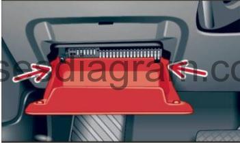
Fuse box in passenger compartment.
fuse box location.
Open the storage compartment. Press the retainers on both sides inwards and fold the storage compartment all the way down.
fuse box diagram.
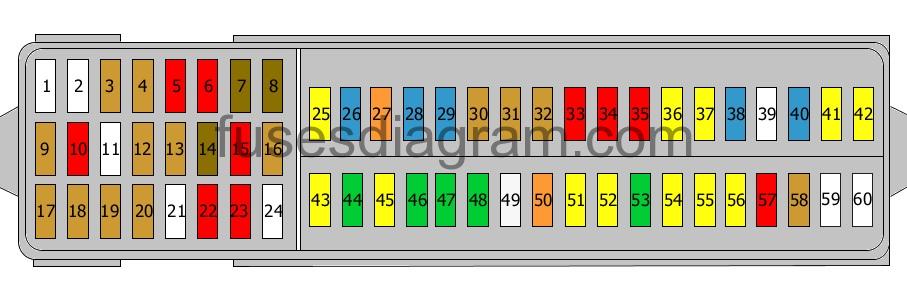
legend.
| Fuses | Amps | Circuits protected |
|---|---|---|
| 1 | Not used | |
| 2 | Not used | |
| 3 | 5A | Glovebox illumination switch Front left vanity light Front right vanity light Glovebox illumination Vanity mirror(s) illumination Sunroof module |
| 4 | 5A | Camera control unit |
| 5 | 10A | Power output control unit for the left headlight |
| 6 | 10A | Power output control unit for the right headlight |
| 7 | 7.5A | Electronic steering column lock control unit |
| 8 | 7.5A | Entry and start authorisation control unit |
| 9 | 5A | Airbag control unit Passenger’s side airbag deactivation light |
| 10 | 10A | 4WD control unit or not used |
| 11 | Not used | |
| 12 | 5A | Mechatronic unit for the dual-clutch gearbox Gear selector control unit |
| 13 | 5A | Oil level and temperature sensor Engine Start and Stop system switch TCS/ESP button Reversing light switch Air-conditioning high-pressure sensor Air quality sensor Climatronic control unit Air-conditioning control unit Power supply relay Power supply relay 2 Warning light(s) Auto-hold button Automatic anti-dazzle rear-view mirror Interior mirror Heated washer jets Seat occupied recognition control unit |
| 14 | 7.5A | Starter relay 1 Starter relay 2 Lighting switch Brake light switch Brake pedal switch Engine control unit Trailer detection control unit Electronic damper control unit ABS control unit Power steering control unit Data bus diagnostic interface Terminal 15 voltage supply relay |
| 15 | 10A | Crankcase breather heater Headlight range control unit Voltage regulator Automatic anti-dazzle rear-view mirror Handbrake control unit Cornering light and headlight range control unit Power socket relay Diagnostic connector (16) Headlight range control Or Mass airflow meter Headlight range control unit Voltage regulator Automatic anti-dazzle rear-view mirror Handbrake control unit Cornering light and headlight range control unit Power socket relay Diagnostic connector (16) Headlight range control |
| 16 | 5A | Parking assistance control unit Lane change assist control unit Lane change assist control unit 2 |
| 17 | 5A | Rear-view camera control unit |
| 18 | 5A | Radio TV tuner Controller area network (CAN) Chip card reader |
| 19 | 5A | On-board supply Voltage regulator Engine control unit |
| 20 | 5A | ABS control unit Air-conditioning control unit Climatronic control unit GPS system |
| 21 | Not used | |
| 22 | 10A | Interior monitoring Alarm horn |
| 23 | 10A | Lighting switch Rain and light sensor Parking brake warning light Diagnostic connector (16) Sunroof module |
| 24 | Not used | |
| 25 | 20A | Fuse box in passenger compartment, fuses 4 – 6 |
| 26 | 15A | Windscreen wiper motor |
| 27 | 40A | Starter relay 1 Starter relay 2 |
| 28 | 15A | Information display control unit Radio Or Information display control unit (7.5A also used) |
| 29 | 15A | Fuse box in passenger compartment, fuses 17, 18 |
| 30 | 5A | CD changer |
| 31 | 5A | Information display control unit |
| 32 | 5A | Control unit with display in the dash panel insert |
| 33 | 10A | Automatic anti-dazzle rear-view mirror |
| 34 | 10A | Central locking, rear doors or not used |
| 35 | 10A | Front central locking or not used |
| 36 | 20A | Power socket Cigarette lighter |
| 37 | 20A | 12V socket |
| 38 | 15A | Terminal 15 voltage supply relay |
| 39 | Not used | |
| 40 | 15A | Trailer detection control unit |
| 41 | 20A | Trailer detection control unit |
| 42 | 20A | Trailer detection control unit |
| 43 | 20A | Headlight washer relay Headlight washer pump |
| 44 | 30A | Heated rear windscreen Heated rear windscreen relay |
| 45 | 20A | Handbrake control unit |
| 46 | 30A | Door control unit, rear right Door control unit, rear left or not used |
| 47 | 30A | Driver’s door control unit Or 4WD control unit (15A also used) or not used |
| 48 | 30A | Front passenger’s door control unit or not used |
| 49 | 25A | Fuel pump relay Fuel pump control unit or not used |
| 50 | 40A | X contact relief relay Fresh-air blower control unit Blower |
| 51 | 20A | Handbrake control unit |
| 52 | 20A | On-board supply Hazard warning light(s) Fuel pump relay |
| 53 | 30A | Climatronic control unit Or Control unit, heated front seats |
| 54 | 20A | Sliding roof control unit |
| 55 | 20A | Sunroof roller blind control unit |
| 56 | 20A | Electronic damper control unit |
| 57 | 10A | Special vehicle control unit Or Power supply relay |
| 58 | 5A | Power supply relay 2 |
| 59 | Not used | |
| 60 | Not used |
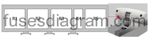
Relay box №1 in passenger compartment.
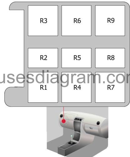
legend.
Relay R1 – Terminal 15 voltage supply relay
Relay R2 – Horn relay
Relay R3 – Power socket relay
Relay R4 – X contact relief relay
Relay R5 – Relay, additional coolant pump or fuel pump relay
Relay R6 – Heated rear windscreen relay
Relay R7 – Automatic anti-dazzle rear-view mirror, Terminal 15 voltage supply relay, Headlight washer relay
Relay R8 – Not used
Relay R9 – Starter relay 1, Starter relay 2
Relay box №2 in passenger compartment.
legend.
Relay R1 – High-output heating relay
Relay R2 – Low-output heating relay
Relay R3 – Not used
Relay R4 – Not used
Relay R5 – Power supply relay, Power supply relay 2
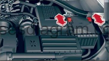
Fuse box in engine compartment Audi Q3.
Release the fuse cover by sliding the two tabs (left and right) forwards.
fuse box diagram (pre 10.2012).
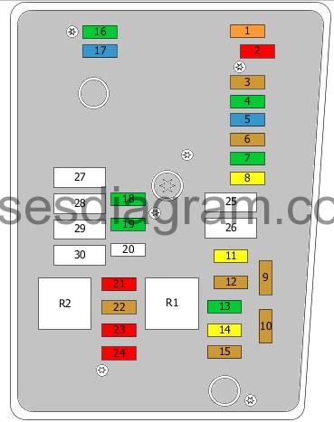
legend.
| Fuses | Amps | Circuits protected |
|---|---|---|
| 1 | 40A | Voltage regulator Fuse box in passenger compartment, fuses 28 – 33 |
| 2 | 10A | Driver’s seat adjustment switch Driver’s seat adjustment Front passenger’s seat adjustment switch Front passenger’s seat adjustment |
| 3 | 5A | On-board supply Battery monitor control unit |
| 4 | 30A | ABS control unit or not used |
| 5 | 15A | Mechatronic unit for the dual-clutch gearbox Gear selector control unit |
| 6 | 5A | Control unit, steering column electronics |
| 7 | 30A | On-board supply |
| 8 | 20A | Front and rear washer pumps Rear windscreen wiper Central locking, rear doors Fuel tank cap Rear power windows lock |
| 9 | 5 | Aerial selection control unit Telephone |
| 10 | 5A | Terminal 30 voltage supply relay Engine control unit |
| 11 | 20A | Additional heater control unit |
| 12 | 5A | Data bus diagnostic interface |
| 13 | 30A | Engine control unit |
| 14 | 20A | Fuel pressure control solenoid Fuel metering solenoid |
| 15 | 5A | Glow plug control unit |
| 16 | 30A | On-board supply |
| 17 | 15 | Horns Horn relay |
| 18 | 30A | Information display control unit Radio Voltage regulator Digital sound package control unit |
| 19 | 30A | Wiper control unit |
| 20 | not used | |
| 21 | 10A | Oxygen sensor in front of the catalytic converter |
| 22 | 5A | Clutch pedal position sensor |
| 23 | 10A | Turbo pressure control solenoid Exhaust gas cooler solenoid Mass airflow meter |
| 24 | 10A | Fuel pump relay Radiator fan control unit Low-output heating relay High-output heating relay Exhaust gas recirculation coolant pump |
| 25 | 40A | ABS control unit or not used |
| 26 | 30A | Fuse box in passenger compartment, fuses 34, 35 |
| 27 | 50A | Glow plug control unit Glow plugs 1 – 4 |
| 28 | not used | |
| 29 | 30A | Driver’s seat adjustment Front passenger’s seat adjustment |
| 30 | 50A | Terminal 15 voltage supply relay Fuse box in passenger compartment, fuses 9 – 16, 25 – 27 |
| R1 | Terminal 30 voltage supply relay | |
| R2 | Glow plug control unit |
Fuse box diagram (since 11.2012).
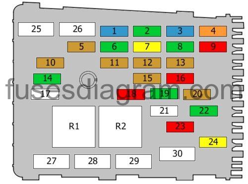
legend.
| Fuses | Amps | Circuits protected |
|---|---|---|
| 1 | 15A | Mechatronic unit for the dual-clutch gearbox Selector lever |
| 2 | 30A | ABS control unit or not used |
| 3 | 15A | Horn relay Horns |
| 4 | 40A | Voltage regulator Fuse box in passenger compartment, fuses 28 – 33 |
| 5 | 5A | On-board supply Battery monitor control unit |
| 6 | 30A | On-board supply |
| 7 | 20A | Front and rear washer pumps |
| 8 | 30A | On-board supply |
| 9 | 10 | Driver’s seat adjustment switch Driver’s seat adjustment Front passenger’s seat adjustment switch Front passenger’s seat adjustment |
| 10 | 5A | Glow plug control unit |
| 11 | 5A | Control unit, steering column electronics |
| 12 | 5A | Aerial selection control unit Telephone |
| 13 | 5A | Terminal 30 voltage supply relay Engine control unit |
| 14 | 30A | Engine control unit |
| 15 | 5A | Data bus diagnostic interface |
| 16 | 10A | Turbo pressure control solenoid EGR cooler change-over valve Mass airflow meter |
| 17 | Not used | |
| 18 | 10A | Oxygen sensor in front of the catalytic converter |
| 19 | 30A | Information display control unit Radio Voltage regulator Digital sound package control unit |
| 20 | 5A | Clutch pedal position sensor |
| 21 | Not used | |
| 22 | 30A | Wiper control unit |
| 23 | 10A | Fuel pump relay Radiator fan control unit Low-output heating relay High-output heating relay Exhaust gas recirculation coolant pump |
| 24 | 20A | Fuel pressure control solenoid Fuel metering solenoid |
| 25 | 30A | Driver’s door control unit Door control unit, rear left |
| 26 | 30A | Front passenger’s door control unit Door control unit, rear right |
| 27 | 50A | Terminal 15 voltage supply relay Fuse box in passenger compartment, fuses 9 – 16, 25 – 27 |
| 28 | 50A | Glow plug control unit Glow plugs 1 – 4 |
| 29 | 30A | Driver’s seat adjustment Front passenger’s seat adjustment |
| 30 | 40A | ABS control unit or not used |
| R1 | Glow plug control unit Or Power supply relay | |
| R2 | Terminal 30 voltage supply relay Or Main relay |
Fuse box in engine compartment.
fuse box diagram (pre 10.2012).
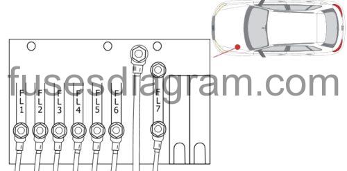
| Fuses | Amps | Circuits protected |
|---|---|---|
| FL1 | 200A | Alternator |
| FL2 | 80A | Power steering control unit |
| FL3 | 50A | Fuse box in passenger compartment, fuses 40 – 42 |
| FL4 | 70A | High-output heating relay |
| FL5 | 80A | Power socket relay Fuse box in passenger compartment, fuses 7, 8, 20 – 24, 43 – 58 Or Fuse box in passenger compartment, fuses 28 – 33 |
| FL6 | 40A | Low-output heating relay |
| FL7 | 60A | Radiator fan control unit |
fuse box diagram (since 11.2012).
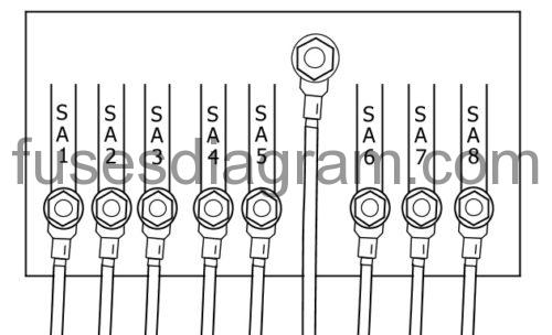
| Fuses | Amps | Circuits protected |
|---|---|---|
| SA1 | 200A | Alternator |
| SA2 | 80A | Power steering control unit |
| SA3 | 50A | Fuse box in passenger compartment, fuses 40 – 42 or not used |
| SA4 | 60A | Radiator fan control unit |
| SA5 | 80A | Fuse box in passenger compartment, fuses 28 – 33 Or Power socket relay Fuse box in passenger compartment, fuses 7, 8, 20 – 24, 43 – 58 or not used |
| SA6 | 70A | High-output heating relay or not used |
| SA7 | 60A | Trailer socket terminal 30 |
| SA8 | 40A | Low-output heating relay Or Condenser |
Electrical component.
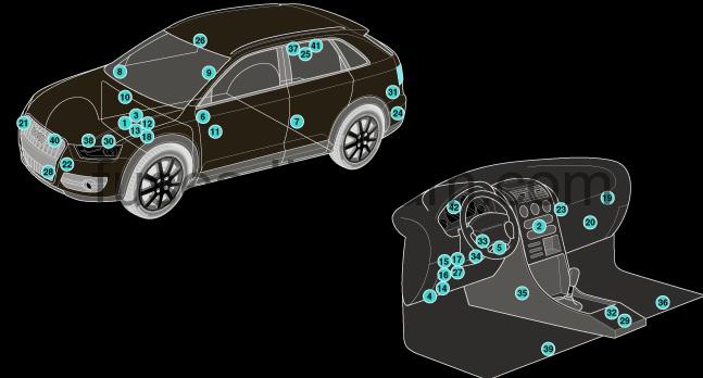
| 1 | ABS control module |
| 2 | AC control module |
| 3 | Battery |
| 4 | Data link connector (DLC) |
| 5 | Diagnostic module |
| 6 | Door function control module, driver |
| 7 | Door function control module, left rear |
| 8 | Door function control module, passenger |
| 9 | Door function control module, right rear |
| 10 | Engine control module (ECM) |
| 11 | Four wheel drive control module – on rear differential |
| 12 | Fuse box/relay plate ,engine bay 1 |
| 13 | Fuse box/relay plate ,engine bay 2 |
| 14 | Fuse box/relay plate, fascia 1 |
| 15 | Fuse box/relay plate, fascia 2 |
| 16 | Fuse box/relay plate, fascia 3 |
| 17 | Fuse box/relay plate, fascia 4 |
| 18 | Glow plug control module – under engine bay fuse box/relay plate 1 |
| 19 | Headlamp level control module |
| 20 | Heater blower speed resistor-in heater box |
| 21 | Horn 1 |
| 22 | Horn 2 |
| 23 | Keyless entry/start control module |
| 24 | Lane change assist control module, left- behind bumper |
| 25 | Lane change assist control module, right- behind bumper |
| 26 | Lane departure warning system control module |
| 27 | Multifunction control module – functions: Exterior lamps, footwell lamps, indicators/hazard warning lamps, interior lamps, luggage compartment lamp |
| 28 | Outside air temperature sensor |
| 29 | Parking brake control module |
| 30 | Power steering control module – on steering rack |
| 31 | Rearview camera control module – LH luggage compartment |
| 32 | Seat heater control module |
| 33 | Steering column function control module – on steering column |
| 34 | Steering column lock control module – on steering column |
| 35 | Supplementary restraint system (SRS) control module |
| 36 | Suspension control module- under carpet |
| 37 | Trailer control module – RH luggage compartment |
| 38 | Transmission control module (TCM) – on gearbox |
| 39 | Voltage stabiliser module –under carpet |
| 40 | Engine coolant blower motor control module |
| 41 | Parking aid control module – RH luggage compartment |
| 42 | Instrumentation control module |