For the Audi Q7 2006, 2007, 2008, 2009, 2010, 2011, 2012, 2013, 2014, 2015 model year.
| Cigarette lighter fuse – (fuse box in Right cockp it : fuse panel, fuse №8/20A) |
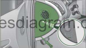
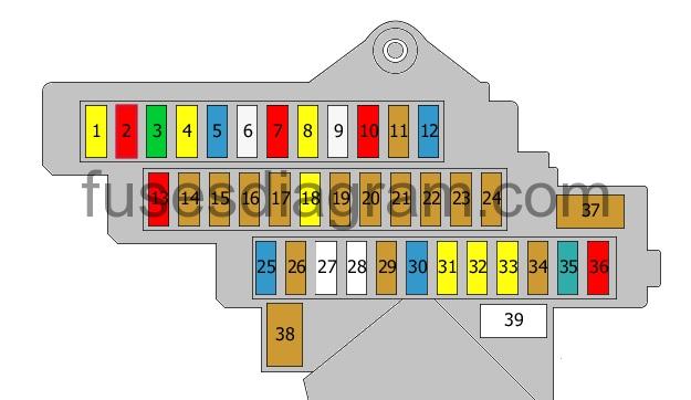
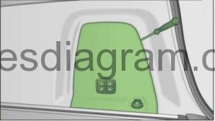
Fuse box in passenger compartment.
Left cockpit: fuse panel cover. Remove the clamp from the rear side of the fuse cover.
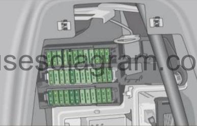
fuse box diagram (pre 05/2009).
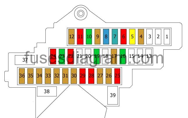
legend.
| Fuses | Amps | Circuits protected |
|---|---|---|
| 1 | Not used | |
| 2 | Not used | |
| 3 | Not used | |
| 4 | 5A | Tyre pressure monitor control unit |
| 5 | 20A | Additional heater control unit |
| 6 | 10A | Driver’s seat adjustment switch |
| 7 | 35A | Driver’s door control unit Front left power window Door control unit, rear left Rear left power window |
| 8 | 15A | Driver’s door control unit Or Driver’s door control unit Rear left door control unit |
| 9 | 5A | Power supply control unit or not used |
| 10 | 30 | Entry and start authorisation control unit Entry and start authorisation switch |
| 11 | 10A | Control unit, steering column electronics |
| 12 | 5A | Interior monitoring Alarm horn |
| 13 | Not used | |
| 14 | Not used | |
| 15 | Not used | |
| 16 | 30A | Wiper motor Wiper control unit |
| 17 | 5A | Rain and light sensor |
| 18 | 25A | Horn relay Horns |
| 19 | 30A | Power supply control unit |
| 20 | 25A | Power supply control unit |
| 21 | 25A | Power supply control unit |
| 22 | 10A | Control unit with display in the dash panel insert Data bus diagnostic interface |
| 23 | 30A | Headlight washer relay |
| 24 | 10A | Diagnostic connector (16) |
| 25 | 10A | Left headlight |
| 26 | 5A | Adaptive cruise control unit Heater |
| 27 | 5A | Information display control unit or not used |
| 28 | 10A | Lane detection control unit Windscreen heater |
| 29 | 10A | System interface control unit Special vehicle control unit Or System interface control unit Special vehicle control unit Multimedia module |
| 30 | 5A | Control unit, steering column electronics Entry and start authorisation control unit Lighting switch Comfort system control unit Trailer detection control unit Brake pedal switch Or Control unit, steering column electronics Entry and start authorisation control unit Lighting switch Comfort system control unit Trailer detection control unit Tyre pressure monitor control unit Brake pedal switch |
| 31 | 5A | Oil level and temperature sensor |
| 32 | 5A | Diagnostic connector (16) |
| 33 | 5A | Automatic anti-dazzle rear-view mirror |
| 34 | 5A | Garage door operation control unit Garage door opener |
| 35 | 5A | Data bus diagnostic interface |
| 36 | 5A | Headlight range control |
| 37 | Not used | |
| 38 | Not used | |
| 39 | Not used |
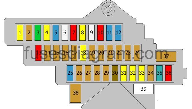
fuse box diagram (since 06/2009).
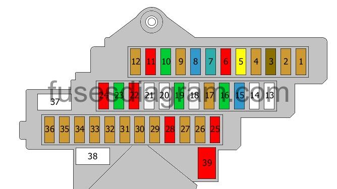
legend.
| Fuses | Amps | Circuits protected |
|---|---|---|
| 1 | 5A | Voltage regulator(s) or not used |
| 2 | 5A | Automatic anti-dazzle rear-view mirror or not used |
| 3 | 7.5A | Information display control unit or not used |
| 4 | 5A | Tyre pressure monitor control unit or not used |
| 5 | 20A | Additional heater control unit |
| 6 | 10A | Driver’s seat adjustment switch |
| 7 | 35A | Driver’s door control unit Front left power window Rear left door control unit Rear left power window |
| 8 | 15A | Driver’s door control unit |
| 9 | 5A | Tyre pressure monitor control unit or not used |
| 10 | 30A | Entry and start authorisation control unit Entry and start authorisation switch |
| 11 | 10A | Control unit, steering column electronics |
| 12 | 5A | Interior monitoring Alarm horn |
| 13 | Not used | |
| 14 | Not used | |
| 15 | 15A | Seat ventilation |
| 16 | 30A | Wiper motor Wiper control unit |
| 17 | 5A | Rain and light sensor |
| 18 | 25A | Horns Horn relay |
| 19 | 30A | Power supply control unit |
| 20 | 25A | Power supply control unit |
| 21 | 25A | Power supply control unit |
| 22 | 10A | Data bus diagnostic interface Or Data bus diagnostic interface Control unit with display in the dash panel insert |
| 23 | 30A | Headlight washer relay |
| 24 | 10A | Diagnostic connector (16) |
| 25 | 10A | Left headlight |
| 26 | 5A | Adaptive cruise control unit Heater |
| 27 | 5A | Information display control unit Or Information display control unit Coolant shut-off valve relay Heating system shut-off valve or not used |
| 28 | 10A | Lane detection control unit Windscreen heater |
| 29 | 5A | Multimedia module |
| 30 | 5A | Control unit, steering column electronics Entry and start authorisation control unit Lighting switch Comfort system control unit Trailer detection control unit Tyre pressure monitor control unit Brake pedal switch |
| 31 | 5A | Oil level and temperature sensor |
| 32 | 5A | Diagnostic connector (16) |
| 33 | 5A | Automatic anti-dazzle rear-view mirror |
| 34 | 5A | Garage door operation control unit Garage door opener |
| 35 | 5A | Data bus diagnostic interface |
| 36 | 5A | Headlight range control |
| 37 | Not used | |
| 38 | Not used | |
| 39 | Not used |
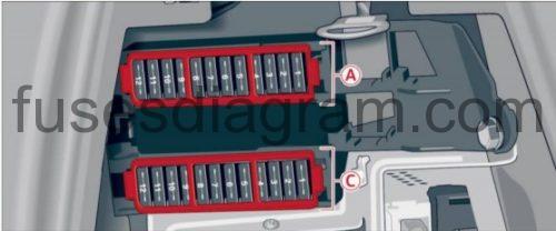
Right cockp it: fuse panel.
fuse box diagram (pre 05/2009).
legend.
| Fuses | Amps | Circuits protected |
|---|---|---|
| 1 | 20A | Rear right heated seat Rear left heated seat |
| 2 | 10A | Automatic transmission control unit (5A also used) |
| 3 | 30A | Heated front seats |
| 4 | 20A | ABS control unit |
| 5 | 15A | Front passenger’s door control unit Or Front passenger’s door control unit Control unit, rear right door |
| 6 | 25A | Additional 12V sockets |
| 7 | 10A | Front passenger’s seat adjustment switch |
| 8 | 20A | Cigarette lighter |
| 9 | 25A | 12V socket Additional 12V socket |
| 10 | 10A | Climatronic control unit Fresh-air blower control unit |
| 11 | 5A | Brake light switch Brake pedal switch ABS control unit or not used |
| 12 | 15A | Power supply control unit 2 |
| 13 | 10A | Right headlight |
| 14 | 5A | Adaptive suspension control unit |
| 15 | 5A | Telephone |
| 16 | 5A | Lane change assist control unit Lane change assist control unit 2 |
| 17 | 5A | Brake light suppression relay Clutch pedal switch |
| 18 | 20A | Automatic transmission control unit (5A also used) |
| 19 | 5A | ABS control unit ESP switch |
| 20 | 5A | Multifunction switch Tiptronic switch Gear selector control unit |
| 21 | 5A | Parking assistance control unit |
| 22 | 5A | Airbag control unit |
| 23 | 5A | Heated seat switches |
| 24 | 5A | Air quality sensor Climatronic control unit Rear climatronic control unit |
| 25 | 15A | Rear windscreen wiper Or Cooler box or not used |
| 26 | 5A | Heated washer jets |
| 27 | Not used | |
| 28 | Not used | |
| 29 | 5A | Communication control unit |
| 30 | 15A | Information display control unit Antenna amplifier Or Information display control unit (7.5A also used) |
| 31 | 20A | Sliding roof control unit |
| 32 | 20A | Sliding roof control unit |
| 33 | 20A | Sunroof roller blind control unit |
| 34 | 5A | Multimedia module CD changer CD player Video system DVD player Or Multimedia module CD changer CD player Video system DVD player Audio connection |
| 35 | 35A | Front right power window Rear right power window |
| 36 | 10A | Climatronic control unit Fresh-air blower control unit |
| 37 | 5A | Control unit for sound transmitted through the vehicle body structure |
| 38 | 5A | Cooler box or not used |
| 39 | Not used |
fuse box diagram (since 06/2009).
legend.
| Fuses | Amps | Circuits protected |
|---|---|---|
| 1 | 20A | Rear right heated seat Rear left heated seat |
| 2 | 10A | Automatic transmission control unit (5A also used) |
| 3 | 30A | Heated front seats |
| 4 | 10A | ABS control unit |
| 5 | 15A | Front passenger’s door control unit Or Front passenger’s door control unit Control unit, rear right door |
| 6 | 25A | Additional 12V sockets |
| 7 | 10A | Front passenger’s seat adjustment switch |
| 8 | 20A | Cigarette lighter |
| 9 | 25A | 12V socket Additional 12V socket |
| 10 | 10A | Climatronic control unit Fresh-air blower control unit |
| 11 | 5A | Brake light switch Brake pedal switch ABS control unit or not used |
| 12 | 15A | Power supply control unit 2 |
| 13 | 10 | Right headlight |
| 14 | 5A | Adaptive suspension control unit |
| 15 | 5A | Telephone |
| 16 | 5A | Lane change assist control unit Lane change assist control unit 2 |
| 17 | 5A | Brake light suppression relay Clutch pedal switch |
| 18 | 20A | Automatic transmission control unit (5A also used) |
| 19 | 5A | ABS control unit ESP switch |
| 20 | 5A | Multifunction switch Tiptronic switch Gear selector control unit |
| 21 | 5A | Parking assistance control unit |
| 22 | 5A | Airbag control unit |
| 23 | 5A | Heated seat switches |
| 24 | 5A | Air quality sensor Climatronic control unit Rear climatronic control unit |
| 25 | 15A | Rear windscreen wiper Or Cooler box or not used |
| 26 | 5A | Heated washer jets |
| 27 | Not used | |
| 28 | Not used | |
| 29 | 5A | Communication control unit |
| 30 | 15A | Information display control unit Antenna amplifier Or Information display control unit (7.5A also used) |
| 31 | 20A | Sliding roof control unit |
| 32 | 20A | Sliding roof control unit |
| 33 | 20A | Sunroof roller blind control unit |
| 34 | 5A | Multimedia module CD changer CD player Video system DVD player Or Multimedia module CD changer CD player Video system DVD player Audio connection |
| 35 | 35A | Front right power window Rear right power window |
| 36 | 10A | Climatronic control unit Fresh-air blower control unit |
| 37 | 5A | Control unit for sound transmitted through the vehicle body structure |
| 38 | 5A | Cooler box or not used |
| 39 | Not used |
Fuse and relay box in passenger compartment.
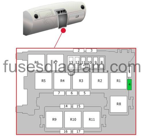
legend.
| Fuses | Amps | Circuits protected |
|---|---|---|
| 1 | Not used | |
| 2 | Not used | |
| 3 | Not used | |
| 4 | 30A | Seat and steering column adjustment control unit with memory Position memory control unit |
| 5 | Not used | |
| 6 | Not used | |
| 7 | Not used | |
| 8 | 40A | Blower |
| 9 | 40A | ABS control unit |
| 10 | 40A | Rear blower |
| 11 | 40A | Heated rear windscreen |
| 12 | 15A | Rear windscreen wiper or not used |
| 13 | 5A | Heated washer jets or not used |
| 14 | Not used | |
| 15 | Not used | |
| 16 | Not used | |
| 17 | Not used | |
| R1 | Adaptive suspension compressor relay | |
| R2 | Terminal 75 voltage supply relay Or Horn relay | |
| R3 | Headlight washer relay | |
| R4 | Brake light suppression relay | |
| R5 | Not used | |
| R6 | Heated rear windscreen relay | |
| R7 | Continued coolant circulation relay Or Coolant shut-off valve relay Or Automatic anti-dazzle rear-view mirror or not used | |
| R8 | Gearbox hydraulic pump relay or not used | |
| R9 | Not used | |
| R10 | Not used | |
| R11 | Not used |
Fuse box in engine compartment Audi Q7.
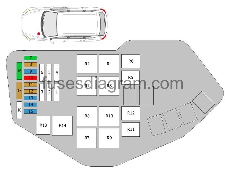
legend.
| Fuses | Amps | Circuits protected |
|---|---|---|
| 1 | 60A | Cooling fan (40A also used) |
| 2 | 40A | Secondary air pump |
| 3 | Not used | |
| 4 | 60A | Cooling fan 2 (40A also used) |
| 5 | 50A | Secondary air pump 2 |
| 6 | Not used | |
| 7 | 30A | Ignition coils Clutch switch (20A also used) |
| 8 | 5A | Cooling fan control unit Cooling fan control unit 2 |
| 9 | 15A | Injectors Engine control unit |
| 10 | 10A | Air-conditioning high-pressure sensor Camshaft timing solenoid Intercooler pump Turbo coolant pump |
| 11 | 5A | Engine control unit |
| 12 | 5A | Crankcase heater |
| 13 | 15A | Secondary air inlet valve Secondary air injection pump relay Swirl control solenoid Oil pressure control valve Coolant circulation pump Coolant circulation pump relay (additional coolant heater) Fuel system diagnostic pump Crankcase breather Fuel metering solenoid Canister purge solenoid |
| 14 | 15A | Oxygen sensors |
| 15 | 15A | Oxygen sensor behind the catalytic converter Oxygen sensor 2 behind the catalytic converter |
| 16 | 30A | Fuel pump control unit |
| 17 | 5A | Engine control unit |
| 18 | Not used | |
| R1 | Starter motor relay Or Power supply relay | |
| R2 | Starter motor, secondary relay Or Main relay | |
| R3 | Power supply relay or not used | |
| R4 | Secondary air pump relay or not used | |
| R5 | Brake servo relay Or Starter motor relay | |
| R6 | Continued coolant circulation relay Or Starter motor, secondary relay | |
| R7 | Not used | |
| R8 | Not used | |
| R9 | Fuel pump relay or not used | |
| R10 | Not used | |
| R11 | Fuel cooling pump relay or not used | |
| R12 | Not used | |
| R13 | Circulation pump relay Or Relay, additional coolant pump | |
| R14 | Main relay or not used |
Fuse box in luggage compartment Audi Q7.
The fuses are located behind the trim on the right side of the luggage compartment.
fuse box diagram (pre 05/2009).
legend.
No. | Equipment | Amps |
|---|---|---|
Fuse holder (black) | ||
1 | Not used | |
2 | Not used | |
3 | Ride height adjustment | 15 |
4 | Not used | |
5 | Advanced Parking System | 5 |
6 | Intelligent power module convenience 2 (right side of vehicle) | 15 |
7 | Intelligent power module convenience 2 (left side of vehicle) | 15 |
8 | Not used | |
9 | Luggage compartment electrical outlet | 20 |
10 | Intelligent power module convenience 1 (right side of vehicle) | 20 |
11 | Convenience control module | 15 |
12 | Intelligent power module convenience 1 (left side of vehicle) | 30 |
Fuse holder (brown) | ||
1 | Not used | |
2 | Not used | |
3 | Not used | |
4 | Not used | |
5 | К-box (MMI), antenna amplifier | 5 |
6 | Not used | |
7 | Navigation | 5 |
8 | Digital Signal Processing (DSP)/ BOSE amplifier | 30 |
9 | Digital Tuner | 5 |
10 | Not used | |
11 | Rear view camera | 5 |
12 | Not used | |
1 | Not used | |
2 | Not used | |
3 | Not used | |
4 | Not used | |
Not used | ||
6 | Soft close | 20 |
Power rear lid | 30 | |
8 | Power rear lid | 30 |
9 | Trailer hitch | 15 |
10 | Trailer hitch (left side of vehicle) | 20 |
| 11 | Trailer hitch (right side of vehicle) | 20 |
No. | Consumer | Amps |
1 | Rear Seat Entertainment | 15 |
2 | AdBlue heater | 30 |
3 | Fuel filler door detection | 5 |
5 | Parking system | 5 |
6 | Intelligent power module convenience 2 (right side of vehicle} | 15 |
7 | Intelligent power module convenience 2 (left side of vehicLe) | 15 |
9 | Luggage compartment electrical outlet | 20 |
10 | Intelligent power module convenience 1 (right side of vehicle) | 20 |
11 | Convenience control module | 15 |
12 | Intelligent power module convenience 1 (left side of vehicle) | 30 |
| 1 | Radio | 7,5/30 |
| 3 | Digital Signal Processing (DSP)/ BOSE amplifier | 30 |
4 | Bang & Olufsen amplifier | 30 |
5 | Ride height adjustment | 15 |
6 | Soft close | 20 |
7 | Power rear lid | 30 |
8 | Power rear lid | 30 |
9 | Trailer hitch | 15 |
10 | Trailer hitch (left side of vehicle) | 20 |
11 | Trailer hitch (right side of vehicle) | 20 |
Electrical component.
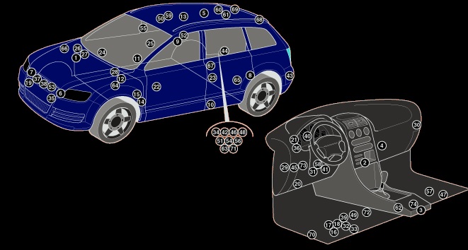
| 1 | ABS control module – in plenum chamber |
| 2 | AC control module (front)- behind heater controls |
| 3 | AC control module (rear) – behind heater controls |
| 4 | AC/heater blower control module – in heater blower housing |
| 5 | Aerial signal amplifier – RH C-post |
| 6 | Airbag crash sensor1 – LH engine bay |
| 7 | Airbag crash sensor2 – RH engine bay |
| 8 | Airbag side assembly crash sensor – behind LH rear side trim panel |
| 9 | Airbag side assembly crash sensor – behind RH rear side trim panel |
| 10 | Airbag side assembly crash sensor-bottom of B-post |
| 11 | Airbag side assembly crash sensor-bottom of B-post |
| 12 | Alarm system horn- under engine bay fuse box/relay plate |
| 13 | Alarm system in car movement sensor- overhead console |
| 14 | Auxiliary heater – behind LH front wheel arch liner |
| 15 | Auxiliary heater control module- incorporated in auxiliary heater |
| 16 | Battery – under seat |
| 17 | Battery control module- under seat |
| 18 | Collision, battery isolator assembly -on battery |
| 19 | Cruise control distance range control module |
| 20 | Data link connector (DLC) |
| 21 | Diagnostic module – behind instrument panel |
| 22 | Door function control module, left front- indoor |
| 23 | Door function control module, left rear- indoor |
| 24 | Door function control module, right front – indoor |
| 25 | Door function control module, right rear- indoor |
| 26 | Engine control module (ECM) (except V8/V12) – in plenum chamber |
| 27 | Engine control module (ECM) (V8/V12)- in plenum chamber |
| 28 | Fuse box/relay plate , engine bay – in plenum chamber |
| 29 | Fuse box/relay plate, fascia 1 |
| 30 | Fuse box/relay plate, fascia 2 |
| 31 | Fuse box/relay plate, fascia 3 |
| 32 | Fuse box/relay plate, under seat 1 |
| 33 | Fuse box/relay plate, under seat2 |
| 34 | Fuse box/relay plate ,load area – behind luggage compartment trim panel |
| 35 | Garage door opener control module – behind bumper |
| 36 | Headlamp level control module |
| 37 | Horn 1 |
| 38 | Horn 2 |
| 39 | Ignition main circuits relay 1 – under LH front seat |
| 40 | Instrumentation control module |
| 41 | Keyless entry/start control module |
| 42 | Keylessentry signal sensor control module – behind luggage compartment trim panel |
| 43 | Lane departure warning system control module (left) – behind bumper |
| 44 | Lane departure warning system control module (right) – behind bumper |
| 45 | Multifunction control module 1 – functions: Fog lamps , hazard warning lamps , headlamp wash , headlamps, horn, indicators, interior lamps , side lamps , steering column adjustment, wipers and washers |
| 46 | Multifunction control module 2 – behind luggage compartment trim panel- functions: Alarm system , central locking , heated rear window , indicators, interior lamps , stoplamps |
| 47 | Multifunction control module 3 – under seat – functions: Alarm system gradient sensor, power steering , sunroof |
| 48 | Multifunction control module 4- behind luggage compartment trim panel- functions: Interior lamps (rear), rear lamps , sunroof control |
| 49 | Multifunction control module 5- under seat – functions: Seat adjustment (with memory), steering column adjustment (with memory) |
| 50 | Multi switch assembly control module – overhead console |
| 51 | Navigation system control module – behind luggage compartment trim panel |
| 52 | Navigation/telephone system aerial-bottomof C-post |
| 53 | Outside air temperature sensor – behind bumper |
| 54 | Parking aid control module – behind luggage compartment trim panel |
| 55 | Rain/ambient light sensor-top centre of windscreen |
| 56 | Rearview camera control module – behind luggage compartment trim panel |
| 57 | Seat adjustment control module, passenger (with memory) – under seat |
| 58 | Steering column function control module |
| 59 | Sunroof control module 1 – behind headlining |
| 60 | Sunroof control module 2- behind headlining |
| 61 | Sun blind control module – behind headlining |
| 62 | Supplementary restraint system (SRS) control module – under centre console |
| 63 | Suspension control module – behind luggage compartment trim panel |
| 64 | Suspension ride height sensor, left front-on suspension |
| 65 | Suspension ride height sensor, left rear- on suspension |
| 66 | Suspension ride height sensor, right front-on suspension |
| 67 | Suspension ride height sensor, right rear-on suspension |
| 68 | Tailgate control module (left)- on tailgate |
| 69 | Tailgate control module (right) – on tailgate |
| 70 | Telephone control module- under carpet |
| 71 | Trailer control module – behind luggage compartment trim panel |
| 72 | Transmission control module (TCM) – in transmission |
| 73 | Tyre pressure monitor control module |
| 74 | Yaw rate/G-force sensor- under centre console |