For the Audi A5 (8T, 8F) 2007, 2008, 2009, 2010, 2011, 2012, 2013, 2014, 2015, 2016 model year.
| Cigarette lighter fuse – (fuse box in luggage compartment, fuse №40/15A) |
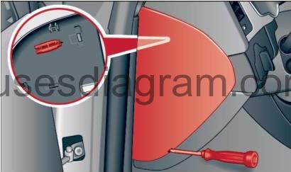
Fuse box in passenger compartment.
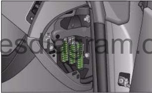
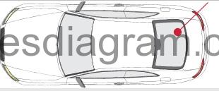
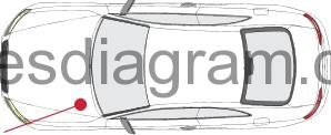
fuse box location.
Left cockpit: fuse panel cover.
fuse box diagram (pre 2009).
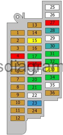
legend (pre 2009).
| Fuse | Amps | Circuits protected |
|---|---|---|
| 1 | 5A | Electric steering control unit |
| 2 | 5A | Clutch pedal position sensor Clutch pedal switch |
| 3 | 5A | Garage door operation control unit Garage door opener |
| 4 | 10A | Lane detection control unit |
| 5 | 5A | Air quality sensor |
| 6 | 5A | Headlight range control potentiometer Headlight range control unit Power output control unit for the right headlight Cornering light and headlight range control unit Headlight range control, left side Headlight range control, right side |
| 7 | 5A | Power output control unit for the left headlight |
| 8 | 5A | Power supply control unit |
| 9 | 5A | Automatic anti-dazzle rear-view mirror |
| 10 | 5A | Selector lever control unit Selector handle lock solenoid |
| 11 | 5A | Heated washer jets |
| 12 | 5A | Refrigerant pressure and temperature sensor |
| 13 | 5A | Circulation pump relay |
| 14 | 5A | Clutch pedal position sensor Clutch pedal switch |
| 15 | 20A | Fuel pressure pump Fuel pump control unit (25A also used) |
| 16 | 5A | Circulation pump relay |
| 17 | 30A | Power supply control unit |
| 18 | 10A | ABS control unit |
| 19 | 25A | Horn relay |
| 20 | 30A | Driver’s door control unit |
| 21 | 30A | Wiper control unit |
| 22 | 25A | ABS control unit |
| 23 | 15A | Driver’s door control unit |
| 24 | 5A | Rain and light sensor |
| 25 | Not used | |
| 26 | Not used | |
| 27 | 10A | Driver’s seat adjustment switch Front passenger’s seat adjustment switch |
| 28 | 35A | Electric steering control unit |
| 29 | Not used | |
| 30 | 35A | Power supply control unit |
| 31 | 30A | Power supply control unit (20A also used) |
| 32 | 30A | Power supply control unit |
| 33 | 20A | Sliding roof control unit |
| 34 | 30A | Power supply control unit |
| 35 | Not used | |
| 36 | 5A | Alarm horn Security alarm |
Fuse box diagram (2010 – 07/2011).
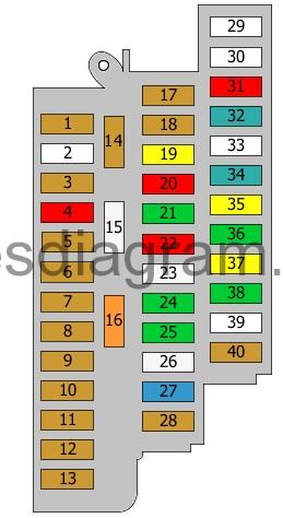
legend (2010 – 07/2011).
| Fuse | Amps | Circuits protected |
|---|---|---|
| 1 | 5A | Electric steering control unit |
| 2 | Not used | |
| 3 | 5A | Garage door operation control unit Garage door opener |
| 4 | 10A | Lane detection control unit |
| 5 | 5A | Air quality sensor |
| 6 | 5A | Headlight range control potentiometer Headlight range control unit Power output control unit for the right headlight Cornering light and headlight range control unit Headlight range control, left side Headlight range control, right side |
| 7 | 5A | Power output control unit for the left headlight |
| 8 | 5A | Power supply control unit |
| 9 | 5A | Adaptive cruise control unit |
| 10 | 5A | Selector lever control unit Selector handle lock solenoid Clutch pedal position sensor |
| 11 | 5A | Heated washer jets |
| 12 | 5A | Refrigerant pressure and temperature sensor |
| 13 | 5A | Connector T18a |
| 14 | 5A | Hazard warning light switch Airbag control unit Seat occupied recognition control unit Hazard warning light illumination |
| 15 | 25A | ABS control unit Fuse box No. 2 in passenger compartment, fuses 17 – 28 Fuse box No. 1 in passenger compartment, fuses 1 – 12 Fuse and relay box in luggage compartment, fuses 37 – 48 |
| 16 | 40A | Starter motor relay Starter motor, secondary relay Fuse 3 in fuse and relay box in engine compartment Fuse 12 in fuse and relay box in engine compartment |
| 17 | 5A | Automatic anti-dazzle rear-view mirror |
| 18 | 5A | Clutch pedal position sensor |
| 19 | 20A | Fuel pressure pump Fuel pump control unit (25A also used) |
| 20 | 10A | Circulation pump relay |
| 21 | 30A | Power supply control unit (15A also used) |
| 22 | 10A | ABS control unit |
| 23 | 25A | Horn relay |
| 24 | 30A | Driver’s door control unit Rear left door control unit |
| 25 | 30A | Wiper control unit |
| 26 | 25A | ABS control unit |
| 27 | 15A | Driver’s door control unit Rear left door control unit |
| 28 | 5A | Rain and light sensor |
| 29 | Not used | |
| 30 | Not used | |
| 31 | 10A | Driver’s seat adjustment switch Front passenger’s seat adjustment switch |
| 32 | 35A | Electric steering control unit |
| 33 | Not used | |
| 34 | 35A | Power supply control unit |
| 35 | 20A | Power supply control unit |
| 36 | 30A | Power supply control unit |
| 37 | 20A | Sliding roof control unit |
| 38 | 30A | Power supply control unit |
| 39 | Not used | |
| 40 | 5A | Alarm horn Security alarm |
Fuse box diagram (since 08/2011).
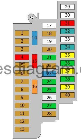
legend (since 08/2011).
| Fuse | Amps | Circuits protected |
|---|---|---|
| 1 | 5A | Electric steering control unit |
| 2 | 5A | ABS control unit |
| 3 | 5A | Rear window roller blind switch TCS/ESP button Parking switch Garage door opener Electric parking brake Auto-hold button Air quality sensor Refrigerant pressure and temperature sensor Garage door operation control unit Heated seat control unit Automatic anti-dazzle rear-view mirror |
| 4 | 10A | Lane detection control unit |
| 5 | 5A | Control unit for sound transmitted through the vehicle body structure |
| 6 | 5A | Headlight range control potentiometer Left headlight Right headlight Headlight range control, left side Headlight range control, right side |
| 7 | 5A | Left headlight |
| 8 | 5A | Adaptive suspension control unit Electronic damper control unit Trailer detection control unit Comfort system control unit 4WD control unit Voltage regulator(s) Electric parking brake control unit |
| 9 | 5A | Adaptive cruise control unit |
| 10 | 5A | Clutch pedal position sensor Selector handle lock solenoid |
| 11 | 5A | Lane change assist control unit Lane change assist control unit 2 |
| 12 | 5A | Power supply control unit |
| 13 | 5A | Airbag control unit Seat occupied recognition control unit Passenger’s side airbag deactivation light |
| 14 | 15A | Windscreen wiper motor |
| 15 | 10A | Fuse box No. 1 in passenger compartment, fuses 1 – 12 |
| 16 | 40A | Starter motor relay Starter motor, secondary relay Fuse and relay box in engine compartment, fuses 3, 12, 15 |
| 17 | Not used | |
| 18 | 5A | Brake light switch Clutch pedal position sensor |
| 19 | 25A | Fuel pump control unit |
| 20 | 5A | Clutch pedal position sensor Reductant metering system Reductant pump Reductant heater |
| 21 | 30A | Power supply control unit Seat ventilation (15A also used) |
| 22 | 5A | ABS control unit |
| 23 | 15A | Horns Horn relay |
| 24 | 30A | Driver’s door control unit |
| 25 | 30A | Wiper control unit |
| 26 | 25A | ABS control unit |
| 27 | 30A | Rear left door control unit |
| 28 | 5A | Rain and light sensor |
| 29 | Not used | |
| 30 | Not used | |
| 31 | 10A | Driver’s seat adjustment switch Front passenger’s seat adjustment switch |
| 32 | 35A | Electric steering control unit |
| 33 | Not used | |
| 34 | 35A | Power supply control unit |
| 35 | 20A | Power supply control unit |
| 36 | 30A | Power supply control unit |
| 37 | 20A | Sliding roof control unit |
| 38 | 30A | Power supply control unit |
| 39 | 20A | Sunroof roller blind control unit |
| 40 | 5A | Alarm horn Security alarm |
Right cockpit: fuse panel with plastic clip.
fuse box diagram.
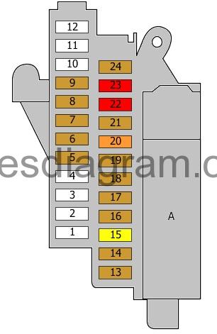
legend.
| Fuse | Amps | Circuits protected |
|---|---|---|
| 1 | Not used | |
| 2 | Not used | |
| 3 | Not used | |
| 4 | Not used | |
| 5 | 5A | Control unit, steering column electronics |
| 6 | 5A | TCS/ESP button Parking assistance or not used |
| 7 | 5A | Diagnostic connector (16) |
| 8 | 5A | Data bus diagnostic interface |
| 9 | 5A | High-output heating relay |
| 10 | Not used | |
| 11 | Not used | |
| 12 | Not used | |
| 13 | 5A | CD changer DVD Audio connection |
| 14 | 5A | Switch module for driving mode or not used |
| 15 | 20A | Multifunction display Radio (5A also used) |
| 16 | 5A | Control unit with display in the dash panel insert |
| 17 | 5A | Data bus diagnostic interface |
| 18 | 5A | Entry and start authorisation switch |
| 19 | 5A | Lighting switch |
| 20 | 40A | Fresh-air blower control unit |
| 21 | 5A | Electronic steering column lock control unit |
| 22 | 10A | Climatronic control unit |
| 23 | 10A | Diagnostic connector (16) |
| 24 | 5A | Control unit, steering column electronics |
| A | Connector |
Fuse and relay box №2 in passenger compartment.
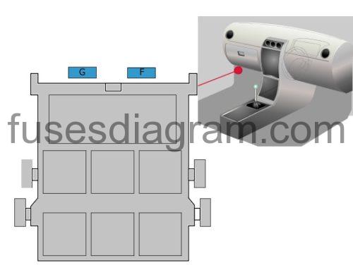
Fuse F (15.0 A) – Passenger’s seat adjustment or Heated front seats (30A also used)
Fuse G (15.0 A) – Driver’s seat adjustment or not used
Fuse and relay box №3 in passenger compartment.
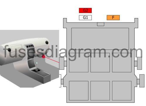
Fuse F (40.0 A) – ABS control unit or not used
Fuse G1 (25.0 A) – ABS control unit or not used
Fuse G2 (10.0 A) – ABS control unit (5A also used) or not used
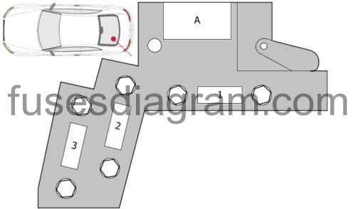
Right luggage compartment: fuse panel with plastic clip.
fuse box diagram (pre 2009).
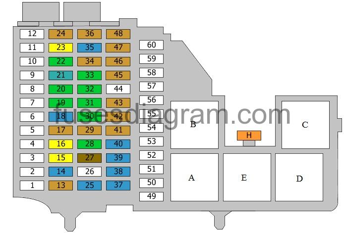
legend (pre 2009).
| Fuse | Amps | Circuits protected |
|---|---|---|
| 1 | Not used | |
| 2 | Not used | |
| 3 | Not used | |
| 4 | Not used | |
| 5 | Not used | |
| 6 | Not used | |
| 7 | Not used | |
| 8 | Not used | |
| 9 | Not used | |
| 10 | Not used | |
| 11 | Not used | |
| 12 | Not used | |
| 13 | 5A | Tyre pressure monitor control unit |
| 14 | 15A | Trailer detection control unit |
| 15 | 20A | Trailer detection control unit |
| 16 | 20A | Trailer detection control unit |
| 17 | 5A | Electric parking brake |
| 18 | 15A | Electronic damper control unit |
| 19 | 30A | Electric parking brake control unit |
| 20 | 30A | Comfort system control unit |
| 21 | 35A | 4WD control unit |
| 22 | 30A | Comfort system control unit |
| 23 | 20A | Comfort system control unit |
| 24 | 5A | GPS system |
| 25 | 15A | DC-AC converter with socket, 12V – 230V (30A also used) |
| 26 | Not used | |
| 27 | 7,5A | Navigation system with CD drive control unit Radio Communication control unit TV tuner Aerial selection control unit Satellite digital audio receiver control unit Connector T18a |
| 28 | 30A | Digital sound package control unit |
| 29 | 5A | Front information control unit |
| 30 | 30A | Additional heater control unit |
| 31 | 30A | Electric parking brake control unit |
| 32 | 30A | Heated seat switches |
| 33 | 30A | Front passenger’s door control unit |
| 34 | 5A | Remote control receiver |
| 35 | 15A | Front passenger’s door control unit |
| 36 | 5A | Rear-view camera control unit |
| 37 | 15A | 12V socket |
| 38 | 15A | 12V socket |
| 39 | 15A | 12V socket |
| 40 | 15A | Cigarette lighter |
| 41 | 5A | Parking assistance control unit |
| 42 | 5A | Connector T18a |
| 43 | 5A | Adaptive cruise control unit |
| 44 | Not used | |
| 45 | 5A | Electric parking brake |
| 46 | 5A | Lane change assist control unit 2 |
| 47 | 5A | Heated seat switches |
| 48 | 5A | Airbag control unit Hazard warning light switch Seat occupied recognition control unit Passenger’s side airbag deactivation light |
| 49 | Not used | |
| 50 | Not used | |
| 51 | Not used | |
| 52 | Not used | |
| 53 | Not used | |
| 54 | Not used | |
| 55 | Not used | |
| 56 | Not used | |
| 57 | Not used | |
| 58 | Not used | |
| 59 | Not used | |
| 60 | Not used | |
| H | 40A | Heated rear windscreen relay |
| Relay A | Heated rear windscreen relay or not used | |
| Relay B | Supplementary radio equipment | |
| Relay C | Heated rear windscreen relay or not used | |
| Relay D | Terminal 15 voltage supply relay Or Not used | |
| Relay E | Power socket relay |
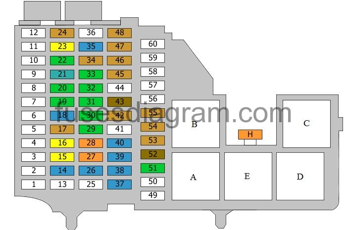
Fuse box diagram (2010 – 07/2011).
legend and fuse box diagram (2010 – 07/2011 PDF).
Fuse box diagram in luggage compartment Audi A5 (since 08/2011).

legend and fuse box diagram (since 08/2011 PDF).
Main fuse box in luggage compartment.
legend.
| Fuse | Amps | Circuits protected |
|---|---|---|
| 1 | 110A | On-board supply Power supply Reductant metering system relay |
| 2 | 110A | On-board supply Power supply ABS control unit |
| 3 | 40A | Special equipment (50A also used) (110A also used) |
| A | Battery isolation/igniter |
Fuse and relay box in engine compartment.
fuse box diagram (pre 07/2011).
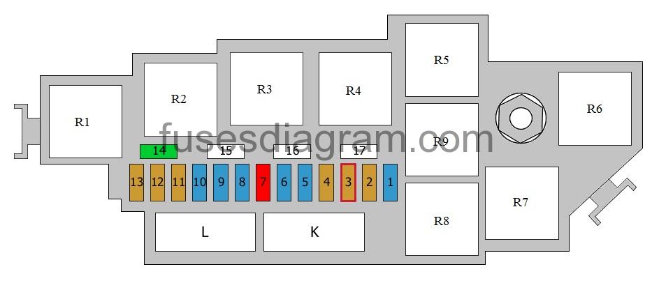
legend (pre 07/2011).
| Fuse | Amps | Circuits protected |
|---|---|---|
| 1 | 15A | Automatic transmission control unit Mechatronic unit for the dual-clutch gearbox |
| 2 | 5A | Oil level and temperature sensor Or Oil level and temperature sensor Fuel metering solenoid Fuel metering solenoid 2 (10A also used) |
| 3 | 5A | Engine control unit Mass airflow meter |
| 4 | 5A | Engine control unit |
| 5 | 15A | MAP-controlled engine cooling thermostat Mass airflow meter Glow plug control unit Secondary air pump relay Throttle control motor with position sensor Inlet manifold valve control motor Low-output heating relay High-output heating relay Secondary air pump relay 2 Turbo pressure control solenoid Crankcase heater Canister purge solenoid Secondary air inlet valve Left electro-hydraulic engine mounting solenoid Right electro-hydraulic engine mounting solenoid Inlet manifold tuning valve Air filter bypass flap valve Fuel pressure control solenoid Fuel metering solenoid Swirl control solenoid Exhaust flap valve EGR cooler change-over valve Fuel metering solenoid 2 Oil pressure control valve Coolant circulation pump Fuel system diagnostic pump (10A also used) (20A also used) |
| 6 | 15A | Engine control unit |
| 7 | 10A | MAP-controlled engine cooling thermostat Valve lift solenoid Continued coolant circulation relay Relay, additional coolant pump Turbo pressure control solenoid Canister purge solenoid Left electro-hydraulic engine mounting solenoid Camshaft timing solenoid Automatic gearbox electro-hydraulic block Turbo bypass solenoid Fuel pressure control solenoid Fuel metering solenoid Swirl control solenoid Outlet camshaft timing solenoid Climatronic coolant shut-off valve Oil pressure control valve Fuel system diagnostic pump Driver’s side power window Inlet manifold tuning motor (15A also used) |
| 8 | 15A | Brake servo relay Or Ignition coils 1 – 8 Climatronic coolant shut-off valve Exhaust gas recirculation coolant pump (5A also used) (10A also used) (20A also used) (30A also used) |
| 9 | 15A | Oxygen sensor behind the catalytic converter Oxygen sensor 2 behind the catalytic converter Relay, additional fuel pump (5A also used) (20A also used) |
| 10 | 15A | Primary heated oxygen sensor Secondary heated oxygen sensor Oxygen sensor behind the catalytic converter (10A also used) |
| 11 | 5A | Cooling fan control unit Cooling fan control unit 2 |
| 12 | 5A | Mass airflow meter Automatic transmission control unit Mechatronic unit for the dual-clutch gearbox |
| 13 | 5A | Oil level and temperature sensor or not used |
| 14 | 30A | Ignition coils 1 – 8 |
| 15 | Not used | |
| 16 | Not used | |
| 17 | Not used | |
| K | 60A | Glow plugs (80A also used) Or Secondary air pump (50A also used) |
| L | Brake vacuum pump Or Secondary air pump 2 (50A also used) | |
| R1 | Glow plug control unit Or Power supply relay | |
| R2 | Starter motor relay Starter motor, secondary relay | |
| R3 | Secondary air pump relay or not used | |
| R4 | Terminal 30 voltage supply relay Or Motronic power supply relay | |
| R5 | Fuel pump relay Relay, additional fuel pump Gearbox cooling relay Or Continued coolant circulation relay Brake servo relay Relay, additional coolant pump | |
| R6 | Secondary air pump relay 2 or not used | |
| R7 | ||
| R8 | ||
| R9 |
Fuse box diagram in engine compartment Audi A5 (since 08/2011).
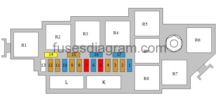
legend and diagram (since 08/2011 PDF).
Fuse box in engine compartment.
pre 07/2011.
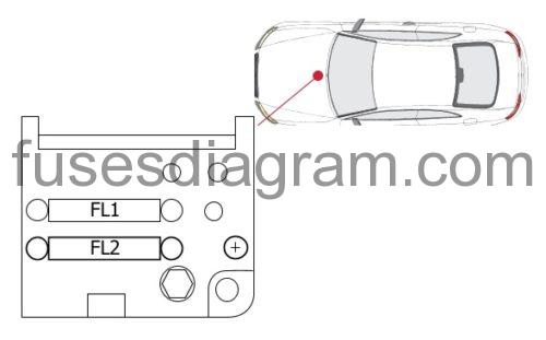
Fuse FL1 (60.0 A) – Radiator fan control unit (40A also used) or not used
Fuse FL2 (40.0 A) – Radiator fan control unit
A – Power socket
Fuse box in engine compartment.
since 08/2011.
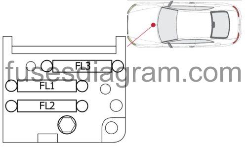
Fuse FL1 (60.0 A) – Radiator fan control unit (40A also used) or not used
Fuse FL2 (40.0 A) – Radiator fan control unit
Fuse FL3 (110.0 A) – Power steering control unit
A – Power socket
Fuse and relay box №1 in engine compartment.
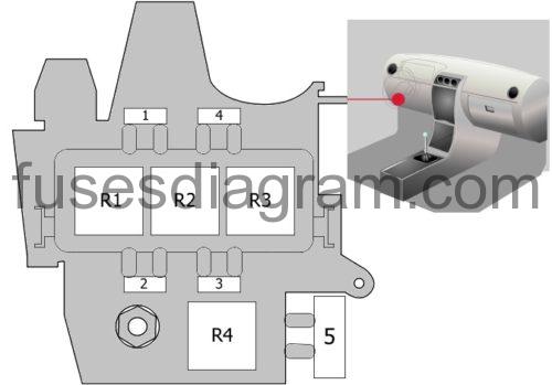
Fuse 5 (40.0 A) – ABS control unit
Relay R1 – Not used
Relay R2 – Horn relay or Horn relay Circulation pump relay or Horn relay Automatic anti-dazzle rear-view mirror
Relay R3 – Terminal 15 voltage supply relay or not used
Relay R4 – Optional equipment
Electrical component.
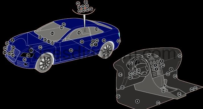
| 1 | ABS control module |
| 2 | AC control module |
| 3 | AC/heater blower control module |
| 4 | Active steering control module |
| 5 | Audio system interface module |
| 6 | Auxiliary heater control module – RH front wheel arch |
| 7 | Battery – under load area floor |
| 8 | Battery control module- under load area floor |
| 9 | CAN data bus gateway control module |
| 10 | Convertible top control module – behind RH rear trim |
| 11 | Cruise control distance range control module |
| 12 | Data link connector (DLC) |
| 13 | Door function control module, driver |
| 14 | Door function control module, passenger |
| 15 | Electric window control module, left rear – behind rear seat |
| 16 | Electric window control module, right rear – behind rear seat |
| 17 | Engine control module (ECM) – in plenum chamber |
| 18 | Engine coolantblower motorcontrol module 1 -near engine coolant blowermotor |
| 19 | Engine coolant blower motor control module 2-near engine coolant blower motor |
| 20 | Four wheel drive control module – under load area floor |
| 21 | Fuel pump control module – on fuel tank |
| 22 | Fuse box/relay plate , engine bay 1 – in plenum chamber |
| 23 | Fuse box/relay plate , engine bay 2 – in plenum chamber |
| 24 | Fuse box/relay plate, fascia 1 |
| 25 | Fuse box/relay plate, fascia 2 |
| 26 | Fuse box/relay plate, fascia 3 |
| 27 | Fuse box/relay plate, footwell 1 |
| 28 | Fuse box/relay plate, footwell 2 |
| 29 | Fuse box/relay plate , load area1 – behind RH rear trim |
| 30 | Fuse box/relay plate, load area2 – under load area floor |
| 31 | Garage door opener control module |
| 32 | Gas discharge headlamp control module 1 |
| 33 | Gas discharge headlamp control module 2 |
| 35 | Horn 1 |
| 36 | Horn 2 |
| 37 | Instrumentation control module |
| 38 | Lane change assist control module 1 – behind bumper |
| 39 | Lane change assist control module 2- behind bumper |
| 40 | Lane departure warning system control module |
| 41 | Multifunction control module 1 |
| 42 | Multifunction control module 2 – behind RH rear trim |
| 43 | Multifunction control module 3 – behind RH rear trim |
| 44 | Multifunction display control module |
| 45 | Outside air temperature sensor |
| 46 | Parking brake control module – behind RH rear trim |
| 47 | Rear view camera control module – behind RH rear trim |
| 48 | Seat control module 1 |
| 49 | Seat control module 2 |
| 50 | Self-parking system control module – behind RH rear trim |
| 51 | Steering column function control module |
| 52 | Steering column lock control module |
| 53 | Sunroof control module |
| 54 | Supplementary restraint system (SRS) control module |
| 55 | Suspension control module – behind RH rear trim |
| 56 | Telephone control module- under seat |
| 57 | Trailer control module – behind RH rear trim |
| 58 | Transmission control module (TCM) – on gearbox |
| 59 | Transmission shift control module |
| 60 | Tyre pressure monitor control module – under carpet |
| 61 | Windscreen wiper control module |