For the Chevrolet Captiva 2006, 2007, 2008, 2009, 2010, 2011 model year.
Fuse box in passenger compartment.
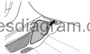
fuse box location.
Interior fuse block is located in the left side of the front passenger foot well.
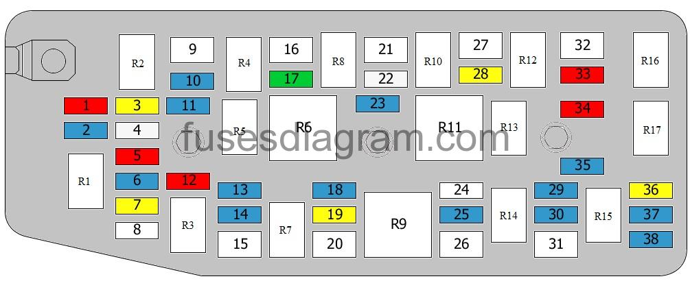
fuse box diagram.
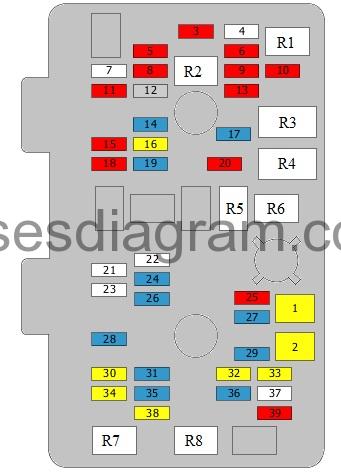
legend.
| Fuses | Amps | Circuits protected |
|---|---|---|
| 1 | 20A | Power window, main switch Sunroof module |
| 2 | 20A | Power window, main switch |
| 3 | 10A | Washer pump relay |
| 4 | Not used | |
| 5 | 10A | Airbag diagnostic module |
| 6 | 10A | Airbag diagnostic module |
| 7 | Not used | |
| 8 | 10A | Rear fog light relay |
| 9 | 10A | Rear fog light relay Fuel pump Fuel level sensor Mirror control unit Clutch switch |
| 10 | 10A | Audio Clock |
| 11 | 10A | Body control unit (BCM) |
| 12 | 2A | Ignition switch Immobiliser |
| 13 | 10A | Instrument cluster Information display control unit Seat belt warning |
| 14 | 15A | Body control unit (BCM) Multimedia control unit |
| 15 | 10A | SSPS |
| 16 | 20A | Body control unit (BCM) |
| 17 | 15A | Heated mirror relay |
| 18 | 10A | Manual air conditioning Automatic temperature control (ATC) control unit AQS sensor Blower, high-speed relay Parking assistance control unit Additional fuse and relay box in engine compartment |
| 19 | 15A | Manual air conditioning Automatic temperature control (ATC) control unit Data link connector (DLC) |
| 20 | 10A | Liftgate relay |
| 21 | Not used | |
| 22 | Not used | |
| 23 | Not used | |
| 24 | 15A | Body control unit (BCM) |
| 25 | 10A | Multimedia control unit |
| 26 | 15A | Body control unit (BCM) |
| 27 | 15A | Front fog light relay |
| 28 | 15A | Instrument cluster Clock Audio Remote control receiver Information display control unit |
| 29 | 15A | TCM |
| 30 | 20A | Heated seat switch |
| 31 | 15A | Body control unit (BCM) |
| 32 | 20A | 12V socket in luggage compartment |
| 33 | 20A | Cigarette lighter |
| 34 | 20A | 12V socket in luggage compartment |
| 35 | 15A | Body control unit (BCM) |
| 36 | 15A | Deadlock relay |
| 37 | Not used | |
| 38 | 20A | Central locking |
| 39 | 10A | Mirror switch Folding mirror |
| R1 | Front washer relay | |
| R2 | Rear fog light relay | |
| R3 | Engine running relay | |
| R4 | Accessory relay | |
| R5 | Liftgate relay | |
| R6 | Heated mirror relay | |
| R7 | Door unlock relay | |
| R8 | Door lock relay |
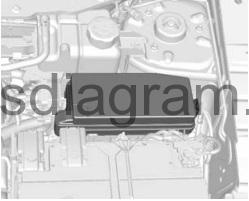
Fuse box in engine compartment Chevrolet Captiva.
fuse box diagram.
legend.
| Fuses | Amps | Circuits protected |
|---|---|---|
| 1 | 10A | Not used |
| 2 | 15A | Not used |
| 3 | 20A | Not used |
| 4 | 25A | Not used |
| 5 | 10A | Right headlight Right tail light |
| 6 | 15A | TCM |
| 7 | 20A | Headlight washer |
| 8 | Not used | Wiper motor |
| 9 | 20A | Wiper motor |
| 10 | 15A | Headlight |
| 11 | 15A | Front fog light relay |
| 12 | 10A | Left headlight Left tail light |
| 13 | 15A | Right headlight Mirror switch |
| 14 | 15A | Left headlight |
| 15 | 30A | Demister |
| 16 | 60A | Fuse and relay box in passenger compartment |
| 17 | 30A | Heated seat switch Electric seats Data link connector |
| 18 | 15A | Left headlight Left tail light Front left parking light/direction indicator Number plate light |
| 19 | 20A | Sunroof module |
| 20 | 40A | Fuse and relay box in passenger compartment |
| 21 | 40A | Fuse and relay box in passenger compartment Blower motor |
| 22 | 25A | Cooling fan relay |
| 23 | 15A | Horn relay |
| 24 | Not used | |
| 25 | 15A | Brake light switch |
| 26 | 30A | Additional cooling fan |
| 27 | 40A | ABS module |
| 28 | 20A | ABS module |
| 29 | 15A | Trailer |
| 30 | 15A | Fuel pump relay |
| 31 | 30A | Main cooling fan |
| 32 | 20A | Starter relay |
| 33 | 10A | Starter relay Main relay |
| 34 | 10A | Air-conditioning compressor relay |
| 35 | 15A | Injector Cooling fan Air-conditioning compressor relay Or Glow plug control unit Cooling fan Air-conditioning compressor relay Additional fuse and relay box in engine compartment Or Ignition coil Injectors (cylinders 1 – 3) Cooling fan Air-conditioning compressor relay |
| 36 | 20A | Engine control unit |
| 37 | 15A | Canister purge solenoid EGR valve Camshaft position sensor Or Throttle actuator Boost pressure regulator solenoid Camshaft position sensor Or Ignition coil Injectors (cylinders 4 – 6) |
| 38 | 15A | Heated oxygen sensors Or Engine control unit Or Heated oxygen sensor Inlet manifold valve control motor Inlet camshaft timing solenoid Outlet camshaft timing solenoid Canister purge solenoid |
| R1 | Headlight washer relay | |
| R2 | Headlight relay, main beam | |
| R3 | Headlight washer relay | |
| R4 | Front fog light relay | |
| R5 | Parking light relay | |
| R6 | Engine running relay | |
| R7 | Demister relay | |
| R8 | Wiper relay | |
| R9 | High-/low-speed wiper relay | |
| R10 | Horn relay | |
| R11 | Fan control relay | |
| R12 | Air-conditioning compressor relay | |
| R13 | Relay, main cooling fan | |
| R14 | Fuel pump relay | |
| R15 | Additional cooling fan relay | |
| R16 | Starter relay | |
| R17 | Main relay |
Additional fuse box in engine compartment (only diesel).
Auxiliary engine room fuse block (Diesel only) is located in the centre of the front panel.
fuse box diagram.
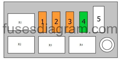
legend.
| Fuses | Amps | Circuits protected |
|---|---|---|
| 1 | 40A | PTC, relay 3 |
| 2 | 40A | PTC, relay 2 |
| 3 | 40A | PTC, relay 1 |
| 4 | 30A | Fuel filter heater relay |
| 5 | 60A | Glow plug control unit |
| R1 | PTC, relay 3 | |
| R2 | PTC, relay 2 | |
| R3 | PTC, relay 1 | |
| R4 | Fuel filter heater relay |