
For the Dodge Durango Second generation 2003, 2004, 2005, 2006, 2007, 2008, 2009 model year.
Interior Fuses.
The fuse block contains blade-type mini-fuses, relays, and circuit breakers for high-current circuits. It is located in the left kick panel. It is accessible through a snap-in cover.
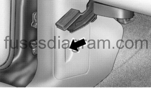
Identifying fuse panel.
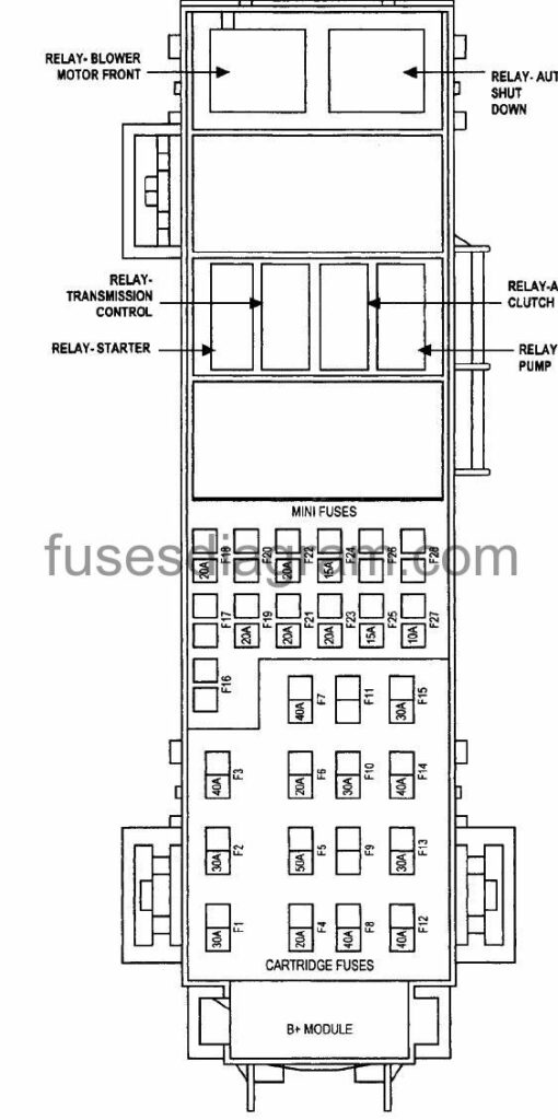
Fuse box diagram

fuses legend.
| № | Fuse/Color | Description |
| F1 | 15 Amp Blue | Instrument Cluster Battery Feed |
| F 2 | 10 Amp Red | Occupant Classification Module (OCM) Battery Feed |
| F3 | 10 Amp Red | Ignition Run/ Start for Controller (NGC), Integrated Power Module(IPM), AC Relay and Fuel Pump Relay |
| F4 | 10 Amp Red | Door Node and Non-Memory Power Mirror Switch Battery Feed |
| F5 | (2) 10 Amp Red | Airbags (2 Fuses in Yellow Holder) |
| F6 | 10 Amp Red | Ignition Run/ Start Unlock |
| F7 | 25 Amp Natural | Radio Battery Feed |
| F8 | 10 Amp Red | Ignition Run/ Start fro Cluster/Transfer Case/Seat Sw. Back lighting |
| F9 | 10 Amp Red | SDAR/DVD Battery Feed |
| F10 | 10 Amp Red | Spare |
| F11 | 10 Amp Red | Heated Mirrors |
| F12 | 20 Amp Yellow | Cluster Battery Feed |
| F13 | 10 Amp Red | Ignition Run HVAC Module/ Heated Rear Glass (EBL) Relay |
| F14 | 10 Amp Red | ABS Module Ignition Run |
| F15 | 15 Amp Blue | Battery Feed Blue Tooth, Compass/Trip Computer (CMTC), Sentry Key Diagnostics |
| F16 | 20 Amp Yellow | Reconfigurable Power Outlets |
| F17 | 20 Amp Yellow | Cigar Lighter Ignition |
| F18 | 10 Amp Red | Spare Fuse |
| F19 | 15 Amp Blue | Heating & Air Conditioning w/ATC Only Battery Feed |
| F20 | 25 Amp Natural | Amplifier Battery Feed |
Underhood Fuses Dodge Durango 2.
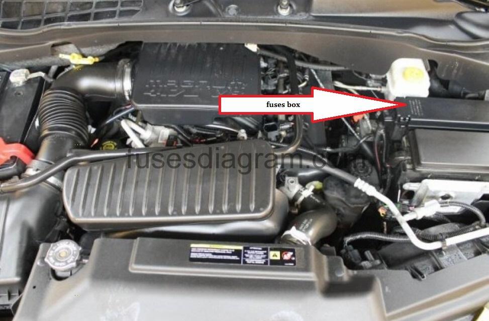
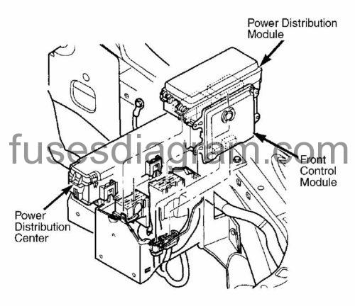
Identifying power distribution center components.
Fuse box diagram
power distribution center legend.
| № | AMPS | FUNCTION |
| 1 | 40A | HVAC Blower |
| 2 | 30A | Power Outlets |
| 3 | 30A | Rr Wiper/Ign R/O |
| 4 | 30A | ABS Pump |
| 5 | 50A | Cabin Htr 1 (Diesel Only) |
| 6 | 50A | ASD |
| 7 | 30A | Rr HVAC (XK) |
| 8 | 40A | Acc Delay/Seats |
| 9 | – | – |
| 10 | 40A | Starter/JB Power |
| 11 | 30A | Cig Ltr/T-Tow |
| 12 | 40A | EBL/Htd Mirror |
| 13 | 40A | JB Power |
| 14 | 50A | Cabin Htr 2 (Diesel Only) |
| 15 | 50A | Cabin Htr 3 (Diesel Only) |
| 16 | 25A | IPM/Coils |
| 17 | – | – |
| 18 | 20A | TCM/AC Clutch |
| 19 | 20A | Ign Sw |
| 20 | 20A | PCM Batt (Gasoline Only) |
| 21 | 30A | ABS Valves |
| 22 | – | – |
| 23 | 20A | FDCM |
| 24 | 20A | Fuel Pump |
| 25 | 20A | FDCM/E-Diff |
| 26 | 15A | Hyd/PCM (Diesel Only) |
| 27 | 15A | Brake/Stop Lamps |
| 28 | 25A | NGC/Injectors |
Power distribution module.
Fuse box diagram
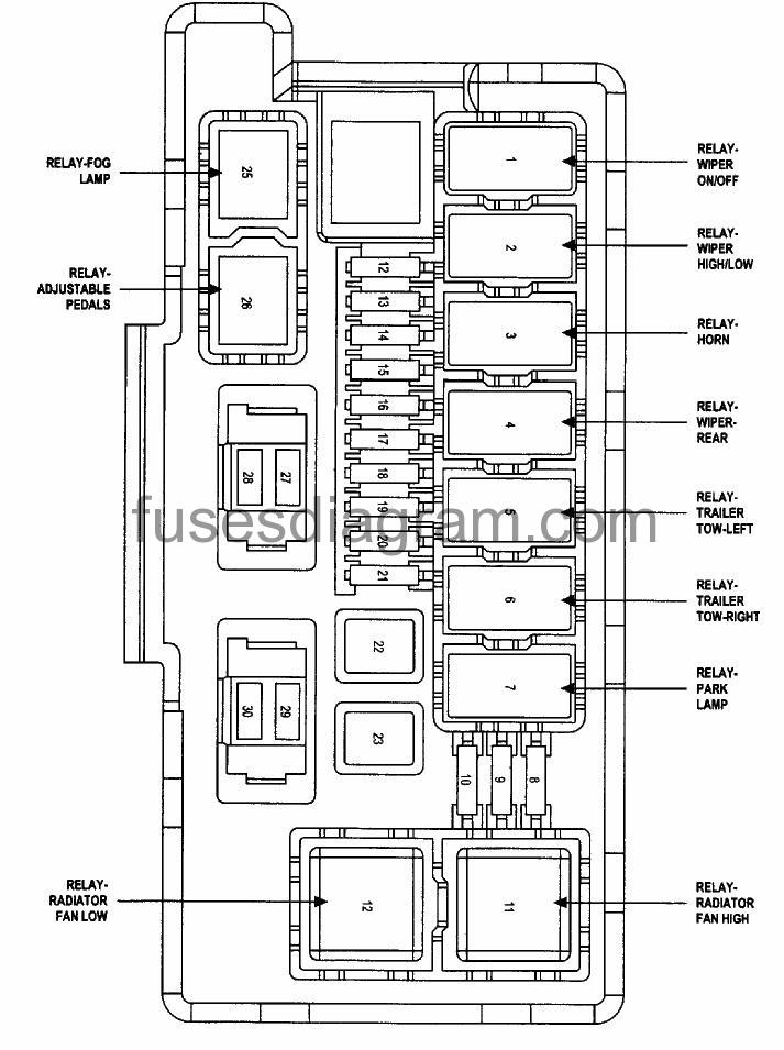
| № | AMPS | FUNCTION |
| 1 | Relay | Wiper On/Off Rly |
| 2 | Relay | Wiper Hi/Lo Rly |
| 3 | Relay | Horn Rly |
| 4 | Relay | Rear Wiper Rly |
| 5 | Relay | Lt. Trailer-Tow Stop/Turn Rly |
| 6 | Relay | Rt. Trailer-Tow Stop/Turn Rly |
| 7 | Relay | Park Lamps Rly |
| 8 | 10A | Lt. Park Lamps |
| 9 | 10A | Trailer-Tow Park Lamps |
| 10 | 10A | Rt. Park Lamps |
| 11 | Relay | Radiator Fan Hi Rly |
| 12 | 20A | Front Control Module (FMC) Batt #4 |
| 13 | 20A | Front Control Module (FMC) Batt #2 |
| 14 | 20A | Adjustable Pedal |
| 15 | 20A | Ft. Fog Lamps |
| 16 | 20A | Horn |
| 17 | 20A | Rear Fogs |
| 18 | 20A | Front Control Module (FMC) Batt #1 |
| 19 | 20A | Lt. Tailer-Tow Stop/Turn |
| 20 | 20A | Front Control Module (FMC) Batt #3 |
| 21 | 20A | Rt. Trailer-Tow Stop/Turn |
| 22 | 30A | Front Control Module (FMC) Batt #5 |
| 23 | 40A | Radiator Fan |
| 24 | Relay | Radiator Fan Lo Rly |
| 25 | Relay | Ft. Fog Lamps Rly |
| 26 | Relay | Adjustable Pedal Rly |
| 27 | 15A | Ignition Off Draw (IOD) #1 |
| 28 | 20A | Ignition Off Draw (IOD) #2 |
| 29 | 10A | ORC (Ign R/S) |
| 30 | 10A | ORC (Ign R/O) |