
For the Hyundai i10 2007, 2008, 2009, 2010, 2011, 2012, 2013 model year.
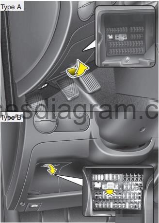
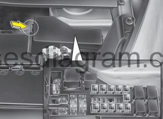
Fuse box in passenger compartment.
Fuse box location.
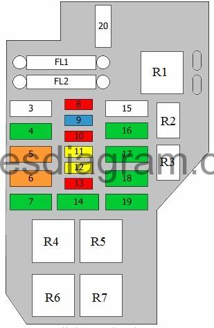
fuse box diagram (-2010).
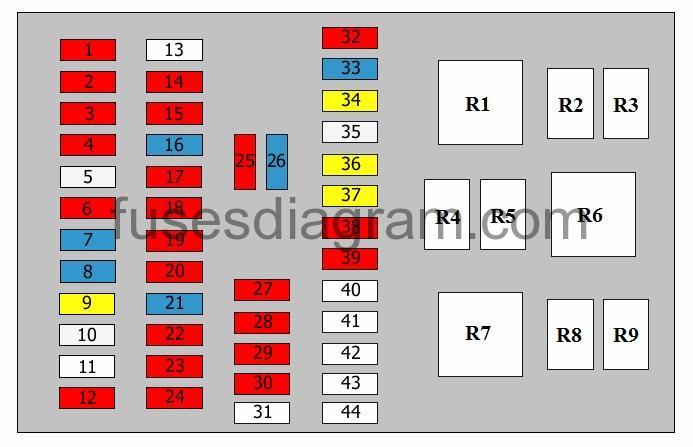
legend.
| Fuse | Amps | Circuits protected |
|---|---|---|
| 1 | 10A | Daylight running system control unit |
| 2 | 10A | Heated rear windscreen Power window relay Lights Light switch Switches Body control unit PTC heater control PTC heater, relay 2 PTC heater, relay 3 SRS control unit PTC Blower relay Blower switch |
| 3 | 10A | Instrument panel Lights |
| 4 | 10A | Lights |
| 5 | 25A | Multifunction switch Rear wiper motor Sunroof motor |
| 6 | 10A | Rear fog light relay Rear fog light switch |
| 7 | 15A | Heated seat switch |
| 8 | 15A | Multifunction switch Rear wiper motor Sunroof motor |
| 9 | 20A | Door lock relay Door unlock relay Body control unit Door lock actuator, front left |
| 10 | 25A | Heated rear windscreen relay Heated rear windscreen |
| 11 | 25A | Not used |
| 12 | 10A | Starter relay Security alarm system relay |
| 13 | 25A | Not used |
| 14 | 10A | ABS/ESP control unit Multi-purpose check connector Electronic stability program (ESP) switch |
| 15 | 10A | Hazard warning switch |
| 16 | 15A | Vehicle speed sensor Mass airflow meter Ignition coil Powertrain control unit (PCM) Engine control unit Pulse generator Fuel filter warning Fuel heater relay |
| 17 | 10A | Rear light switch ATM Transaxle range switch Pulse generator |
| 18 | 10A | Instrument panel |
| 19 | 10A | SRS control unit |
| 20 | 10A | Instrument panel Body control unit Generator EPS control unit |
| 21 | 15A | Cigarette lighter |
| 22 | 10A | Clock Audio Exterior mirror fold in/fold out feature |
| 23 | 10A | Air-conditioning switch |
| 24 | 10A | Engine control unit Powertrain control unit (PCM) Heated rear windscreen switch |
| 25 | 10A | SRS control unit Interior lights Instrument panel PTC heater control Rear fog light switch Clock Door open Luggage compartment light Overhead console |
| 26 | 15A | Audio |
| 27 | 10A | Brake light switch |
| 28 | 10A | Hazard warning switch Hazard warning light relay |
| 29 | 10A | Horns Horn relay |
| 30 | 10A | Front fog light relay Front fog light switch Front fog lights |
| 31 | 25A | Not used |
| 32 | 10A | Spare fuse |
| 33 | 15A | Spare fuse |
| 34 | 20A | Spare fuse |
| 35 | 25A | Spare fuse |
| 36 | 20A | Power windows, main switch |
| 37 | 20A | Power windows, main switch Passenger’s power window switch |
| 38 | 10A | Rear left light Daylight running system control Lighting Number plate light |
| 39 | 10A | Rear lights Lighting |
| 40 | diode | |
| 41 | diode | |
| 42 | diode | |
| 43 | diode | |
| 44 | diode | |
| R1 | Power window relay | |
| R2 | Horn relay | |
| R3 | Front fog light relay | |
| R4 | Not used | |
| R5 | Tail light(s) relay | |
| R6 | Flasher unit | |
| R7 | Blower relay | |
| R8 | Rear heater relay | |
| R9 | Rear fog light relay |
Fuse box diagram (2011-).
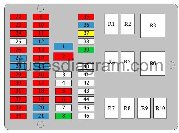
legend.
| Fuse | Amps | Circuits protected |
|---|---|---|
| 1 | 15A | Audio DC-DC converter |
| 2 | 10A | Body control unit (BCM) Door open Diagnostic connector Luggage compartment light(s) Interior lights Fog light switch Heater control unit Digital clock Instrument panel |
| 3 | 25A | Power windows, main switch Passenger’s power window switch Switch, rear left power window(s) |
| 4 | 25A | Power windows, main switch Passenger’s power window switch Switch, rear right power window(s) |
| 5 | 10A | Left headlight Daylight running system Number plate light Rear left combination light |
| 6 | 10A | Right headlight Number plate light Rear right combination light Hazard warning light switch Rheostat Instrument panel Rear fog light switch Daylight running system Blower switch Heater control unit Headlight levelling switch Audio Power windows, main switch Front fog light switch Digital clock Heated rear windscreen switch Intelligent Stop and Go (ISG) switch Automatic transmission shift lever Heated front passenger’s seat switch Diode Driver’s seat heater switch Rear fog light switch Buzzer Heated rear windscreen relay |
| 7 | 25A | Sunroof motor Driver’s door lock actuator Body control unit (BCM) Integrated circuit module (ICM) relay box in passenger compartment, relays R1, R2 |
| 8 | 30A | Heated rear windscreen relay |
| 9 | 10A | Engine control unit Malfunction indicator Front wiper motor |
| 10 | 10A | Brake pedal switch ESP switch EPS ABS Diagnostic connector |
| 11 | 10A | Hazard warning light switch |
| 12 | 15A | Engine control unit DC-DC converter Vehicle speed sensor Ignition coil Condenser Pulse generator Transaxle range switch |
| 13 | 10A | Rear parking sensor Reversing light switch |
| 14 | 10A | Instrument panel |
| 15 | 15A | Supplemental restraint system (SRS) |
| 16 | 10A | Instrument panel Heater control unit Body control unit (BCM) Seat belts |
| 17 | 10A | EPS control unit |
| 18 | 10A | Audio Digital clock DC-DC converter |
| 19 | 10A | Front and rear accessory sockets |
| 20 | 15A | Cigarette lighter |
| 21 | 15A | Engine control unit Starter relay Transaxle range switch Integrated circuit module (ICM) relay box in passenger compartment, relay R4 |
| 22 | 10A | Instrument panel Fuse and relay box in engine compartment, relays R3, R4 |
| 23 | 10A | Daylight running system |
| 24 | 10A | Headlights Headlight levelling switch Body control unit (BCM) Heater control unit Air-conditioning dual and high-pressure switch Heated rear windscreen relay Diode Power window switches Fuse and relay box in engine compartment, relay R8 |
| 25 | 25A | Front wiper motor Multifunction switch |
| 26 | 10A | Rear fog light relay |
| 27 | 15A | Heated front seat(s) switch |
| 28 | 15A | Rear wiper motor Sunroof motor Multifunction switch |
| 29 | 10A | Brake pedal switch Brake pedal relay |
| 30 | 10A | Hazard warning light switch Integrated circuit module (ICM) relay box in passenger compartment, relay R5 |
| 31 | 10A | Horn relay Integrated circuit module (ICM) relay box in passenger compartment, relay R4 |
| 32 | 10A | Front fog light relay |
| 33 | 10A | Heated rear windscreen switch Heater control unit Engine control unit Electric mirror controls |
| 34 | 10A | Transaxle range switch Instrument panel Engine control unit Rear combination light(s) Reversing light switch |
| 35 | 15A | spare fuse |
| 36 | 20A | spare fuse |
| 37 | 25A | spare fuse |
| 38 | 30A | spare fuse |
| 39 | spare fuse | |
| 40 | spare fuse | |
| 41 | spare fuse | |
| 42 | spare fuse | |
| 43 | spare fuse | |
| 44 | spare fuse | |
| 45 | spare fuse | |
| 46 | spare fuse | |
| R1 | Heated driver’s seat control relay | |
| R2 | Power window relay | |
| R3 | Brake pedal relay | |
| R4 | Horn relay | |
| R5 | Front fog light relay | |
| R6 | Flasher relay | |
| R7 | Heated passenger’s seat control relay | |
| R8 | Tail light relay | |
| R9 | Heated rear windscreen relay | |
| R10 | Rear fog light relay |
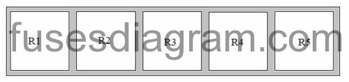
Integrated cicuit modul (ICM) relay box in passenger compartment (2011-).
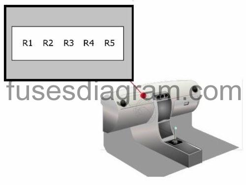
Relay R1 – Door lock relay
Relay R2 – Door unlock relay
Relay R3 – Alarm horn relay
Relay R4 – Alarm relay
Relay R5 – Hazard warning light relay
Fuse box in engine compartment.
fuse box location.
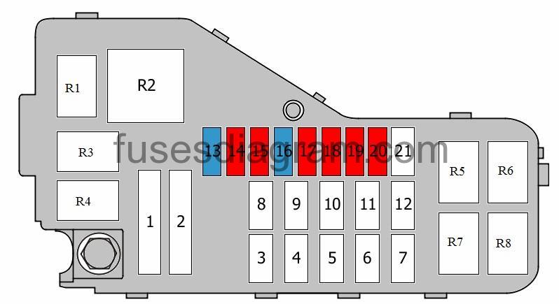
fuse box layout (-2010).
legend.
| Fuse | Amps | Circuits protected |
|---|---|---|
| FL1 | 80A | EPS control unit |
| FL2 | 100A | Generator (125A also used) |
| 3 | 50A | Heated window Door lock Sunroof Hazard warning system Horn Front fog light(s) Front fog light switch |
| 4 | 30A | Power window relay |
| 5 | 40A | ABS/ESP control unit Multi-purpose check connector |
| 6 | 40A | ABS/ESP control unit Multi-purpose check connector |
| 7 | 30A | Blower relay |
| 8 | 10A | Engine control unit Powertrain control unit (PCM) |
| 9 | 15A | Cooling fan 1 relay Cooling fan 2 relay Variable geometry turbine (VGT) Air-conditioning relay Engine control unit Powertrain control unit (PCM) Idle speed actuator Variable geometry turbine (VGT) EGR Glow plug relay PTC heater, relay 1 Swirl control solenoid Camshaft position sensor Immobiliser control unit Injectors (cylinders 1 – 4) |
| 10 | 10A | Powertrain control unit (PCM) Purge control valve Crankshaft position sensor Oxygen sensor behind the catalytic converter Oxygen sensor in front of the catalytic converter Camshaft position sensor Immobiliser control unit Light switch Oxygen sensor |
| 11 | 20A | Engine control unit |
| 12 | 20A | Fuel pump relay Fuel pump control Fuel sender Fuel pump |
| 13 | 10A | Air-conditioning relay Air-conditioning compressor |
| 14 | 30A | Fuel filter heater relay |
| 15 | 50A | Ignition switch Starter relay |
| 16 | 30A | Ignition switch |
| 17 | 30A | Tail light relay Power connector Air conditioning |
| 18 | 30A | Main relay Engine control unit Powertrain control unit (PCM) Fuel pump relay |
| 19 | 30A | Cooling fan 1 relay Cooling fan 2 relay |
| 20 | Fuse puller | |
| R1 | Main relay | |
| R2 | Fuel pump relay Additional relay, fuel pump | |
| R3 | Fuel filter heater relay | |
| R4 | Starter relay | |
| R5 | Air-conditioning relay | |
| R6 | Cooling fan 1 relay | |
| R7 | Cooling fan 2 relay |
Fuse box layout (2011-) (engine compartment).
| Fuse | Amps | Circuits protected |
|---|---|---|
| 1 | 80A | EPS control unit |
| 2 | 100A | Alternator |
| 3 | 50A | Fuse and relay box in passenger compartment, fuses 7, 8 |
| 4 | 40A | Fuse and relay box in passenger compartment, relay R2 |
| 5 | 40A | ABS ESP Diagnostic connector |
| 6 | 40A | ABS EPS |
| 7 | 40A | Blower relay |
| 8 | 50A | Ignition switch |
| 9 | 40A | Ignition switch |
| 10 | 50A | Fuse and relay box in engine compartment, fuse 18 Fuse and relay box in engine compartment, relay R7 Fuse and relay box in passenger compartment, fuses 1, 2, 29 – 32 |
| 11 | 30A | Fuse and relay box in engine compartment, fuse 15 Fuse and relay box in engine compartment, relay R2 |
| 12 | 40A | Fuse and relay box in engine compartment, relay R6 |
| 13 | 15A | Fuse and relay box in engine compartment, relay R1 |
| 14 | 10A | Heater control unit Air-conditioning switch |
| 15 | 10A | Engine control unit |
| 16 | 15A | Fuse and relay box in engine compartment, relays R1, R6 Fuel injectors Idle speed stepper motor Engine control unit Or Fuse and relay box in engine compartment, relays R1, R6 Engine control unit Inlet camshaft timing solenoid Outlet camshaft timing solenoid Idle speed control motor Fuel injectors Canister purge solenoid |
| 17 | 10A | Engine control unit Immobiliser control unit Oxygen sensor in front of the catalytic converter Oxygen sensor behind the catalytic converter Canister purge solenoid Hall/MRE sensor on the camshaft Hall/MRE sensor on the crankshaft Or Engine control unit Hall/MRE sensor on the inlet camshaft Hall/MRE sensor on the outlet camshaft Immobiliser control unit Oxygen sensor in front of the catalytic converter Oxygen sensor behind the catalytic converter |
| 18 | 10A | Fuse and relay box in engine compartment, relay R5 |
| 19 | 10A | Left headlights |
| 20 | 10A | Right headlights |
| 21 | 30A | Fuse and relay box in engine compartment, fuses 13, 15, 20 |
| R1 | Fuel pump relay | |
| R2 | Main relay | |
| R3 | Dipped beam relay | |
| R4 | Main beam relay | |
| R5 | Air-conditioning relay | |
| R6 | Blower relay | |
| R7 | Starter relay | |
| R8 | Radiator fan relay |
Relay box in engine compartment.
Relay R1 – Hazard warning light relay
Relay R2 – Door unlock relay
Relay R3 – Door lock relay
Relay R4 – Security alarm system relay
Relay R5 – Alarm horn relay