For the Hyundai Grandeur (TG), Hyundai Azera 2006, 2007, 2008, 2009, 2010, 2011 model year.
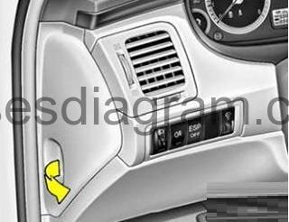
Fuse box in passenger compartment.
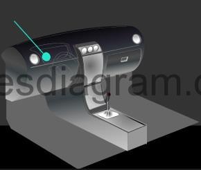
Fuse box location.
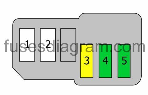
fuse box diagram.
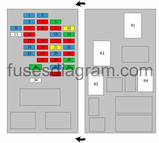
legend.
| Fuse | Amps | Circuits protected |
|---|---|---|
| 1 | 15A | Cigarette lighter |
| 2 | 15A | Tilt and telescopic module Sport mode switch |
| 3 | 15A | Body control unit (BCM) |
| 4 | 10A | Front fog light relay Rear left combination light Number plate light Left headlight |
| 5 | Not used | |
| 6 | 15A | Rear power outlet |
| 7 | 10A | Comfort system control unit |
| 8 | 10A | Rear right combination light Number plate light Right headlight Rheostat |
| 9 | 10A | Instrument cluster Body control unit (BCM) Comfort system control unit Rain sensor Position memory control unit Power windows, main switch |
| 10 | 20A | Fuel filler flap Fuel filler cap |
| 11 | 25A | Front washer relay Wiper relay Wiper motor |
| 12 | 10A | Headlight relay High Intensity Discharge (HID) relay Headlight levelling actuator(s) Headlight washer relay |
| 13 | 15A | Warning buzzer |
| 14 | 30A | Driver’s seat lumbar support switch Passenger’s seat lumbar support switch Position memory control unit Driver’s seat control unit |
| 15 | 10A | Air-conditioning control unit Blower relay Blower motor |
| 16 | 10A | Heated front seat(s) switch |
| 17 | 10A | Exterior mirror Folding mirror Air-conditioning control unit |
| 18 | 10A | Automatic transmission key lock control unit Audio Position memory switch Accessory relay Body control unit (BCM) Digital clock Seat belt warning |
| 19 | 15A | Data link connector Air-conditioning control unit Instrument cluster Multifunction switch Tilt and telescopic module Body control unit (BCM) Open door warning light Interior light(s) Door light(s) Position memory control unit |
| 20 | 10A | Instrument cluster ESP switch Body control unit (BCM) Automatic transmission key lock control unit Yaw rate sensor Multifunction switch |
| 21 | 20A | Keyless entry control unit Power windows, main switch |
| 22 | 15A | Audio |
| 23 | 15A | Not used |
| 24 | 10A | Air-conditioning control unit Tilt and telescopic module Rheostat Electrochromatic mirror Sunroof motor AQS sensor Ambient air temperature sensor |
| 25 | 15A | Rear fog light relay |
| 26 | 10A | Transaxle range switch Security alarm system relay |
| 27 | 10A | PTC heater relay Fuel filter relay |
| 28 | 10A | Instrument cluster |
| 29 | 30A | Power window control unit, front left Switch, rear left power window(s) |
| 30 | 15A | Fuse and relay box in passenger compartment, fuses 19, 22 |
| 31 | 30A | Airbag switch SRS control unit |
| 32 | 10A | Front right power window Switch, rear right power window(s) |
| 33 | Spare fuse | |
| 34 | ||
| R1 | Blower relay | |
| R2 | Demister relay | |
| R3 | Tail light(s) relay | |
| R4 | Fuel filler cap relay |
Intergrated circuit module (ICM) relay box in passenger compartment.
reley box diagram.
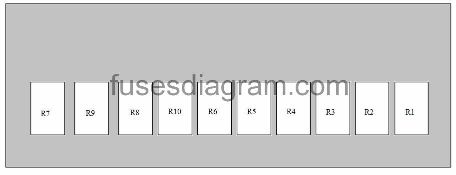
Relay R1 – Alarm relay
Relay R2 – Alarm horn relay
Relay R3 – Wiper relay
Relay R4 – Front washer relay
Relay R5 – Not used
Relay R6 – Headlight washer relay
Relay R7 – Daylight running system relay
Relay R8 – Accessory relay
Relay R9 – Power outlet relay or not used
Relay R10 – Rear fog light relay
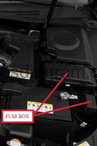
Fuse box in engine compartment.
fuse box location.
fuse box layout.
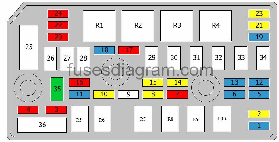
legend.
| Fuse | Amps | Circuits protected |
|---|---|---|
| 1 | 15A | Horn relay |
| 2 | 20A | Tail light(s) relay |
| 3 | 10A | Powertrain control unit (PCM) or not used |
| 4 | 10A | TCM or not used |
| 5 | 15A | Alarm horn relay Daylight running system relay |
| 6 | 15A | Front fog light relay |
| 7 | 10A | Air-conditioning relay |
| 8 | 20A | Fuel pump relay |
| 9 | Not used | |
| 10 | 20A | Automatic transmission control relay |
| 11 | 15A | Brake light switch |
| 12 | 15A | High Intensity Discharge (HID) relay |
| 13 | 15A | Sunroof motor |
| 14 | 20A | Headlight washer relay |
| 15 | 20A | Headlight relay, main beam |
| 16 | 10A | Powertrain control unit (PCM) TCM Generator |
| 17 | 10A | Injector Air-conditioning relay Cooling fan relay Oxygen sensor |
| 18 | 15A | Mass airflow meter Powertrain control unit (PCM) Immobiliser control unit Oil control valve Inlet manifold tuning valve Camshaft position sensor Exhaust gas recirculation actuator Canister purge solenoid |
| 19 | 15A | Oxygen sensor Fuel pump relay Powertrain control unit (PCM) Variable geometry turbine (VGT) |
| 20 | 10A | Brake light switch Transaxle range switch Pulse generator Vehicle speed sensor |
| 21 | 20A | Ignition coil Condenser or not used |
| 22 | 10A | Powertrain control unit (PCM) Engine control unit Mass airflow meter |
| 23 | 20A | Headlight relay, dipped beam |
| 24 | 10A | ABS control unit Multi-purpose check connector ESP control unit |
| 25 | Not used | |
| 26 | 40A | ABS control unit ESP control unit Multi-purpose check connector |
| 27 | 20A | ABS control unit ESP control unit Multi-purpose check connector |
| 28 | 40A | Fuse and relay box in passenger compartment, fuses 2, 3, 7, 10, 13, 14 Or Fuse and relay box in passenger compartment, fuses 1, 4, 8, 10, 11, 14 |
| 29 | 40A | Demister relay |
| 30 | 40A | Blower relay |
| 31 | 40A | Fuse and relay box in passenger compartment, fuses 29, 32 Or Fuse and relay box in passenger compartment, fuses 28, 31 |
| 32 | 40A | Starter relay Ignition switch |
| 33 | 30A | Engine control relay Powertrain control unit (PCM) Engine control unit |
| 34 | 30A | Power connector Fuse and relay box in passenger compartment, fuses 21, 25 Or Power connector Fuse and relay box in passenger compartment, fuses 21, 24 |
| 35 | 30A | Ignition switch |
| 36 | 150A | Fuse and relay box in engine compartment, fuses 26, 27, 29, 30 |
| R1 | Headlight relay, dipped beam | |
| R2 | Headlight relay, main beam | |
| R3 | Starter relay | |
| R4 | Main relay | |
| R5 | Automatic transmission control relay | |
| R6 | Fuel pump relay | |
| R7 | Wiper relay | |
| R8 | Air-conditioning relay | |
| R9 | Fog light relay | |
| R10 | Horn relay |
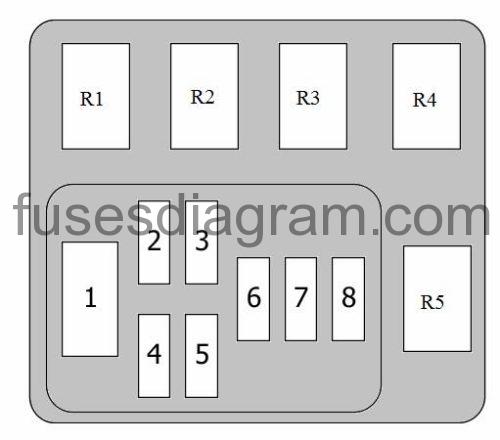
Additional fuse box in engine compartment.
| Fuse | Amps | Circuits protected |
|---|---|---|
| 1 | 80A | Glow plug relay |
| 2 | 50A | PTC heater, relay 1 |
| 3 | 50A | PTC heater, relay 2 |
| 4 | 50A | PTC heater, relay 3 |
| 5 | 40A | Fuel filter relay |
| 6 | 30A | Not used |
| 7 | 20A | Not used |
| 8 | 30A | Not used |
| R1 | Glow plug relay | |
| R2 | PTC heater, relay 1 | |
| R3 | PTC heater, relay 2 | |
| R4 | PTC heater, relay 3 | |
| R5 | Fuel filter relay |
Additional fuse box in engine compartment.
| Fuse | Amps | Curcuits protected |
|---|---|---|
| 1 | 60A | Not used |
| 2 | 60A | Cooling fan relay |
| 3 | 20A | Accessory relay (25A also used) |
| 4 | 30A | Amplifier |
| 5 | 30A | Control unit, heated front seats |