
For the Hyundai Getz 2003, 2004, 2005, 2006, 2007, 2008, 2009, 2010, 2011 model year.
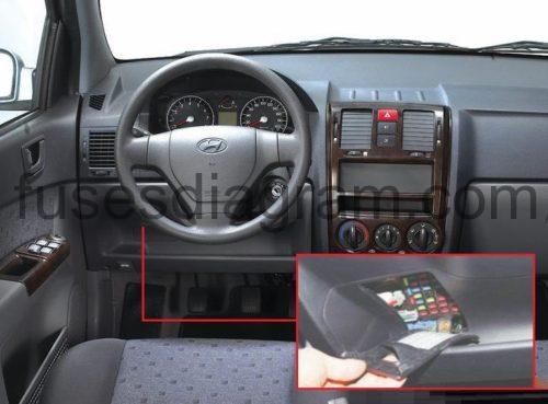
Fuse box in passenger compartment.
Fuse box location.
fuse box diagram.

legend.
| Fuse | Amps | Circuits protected |
|---|---|---|
| 1 | 10A | Air-conditioning switch |
| 2 | 10A | Rear left combination light Front left parking light |
| 3 | 10A | Instrument panel |
| 4 | 10A | Electric mirror controls Audio Electric mirror switch Folding mirror Digital clock |
| 5 | 10A | Transaxle range switch Hazard warning switch Reversing light switch |
| 6 | 10A | Front right parking light Rear right combination light Number plate light(s) |
| 7 | 10A | Electronic time and alarm control unit Pre-excitation resistor Instrument panel Seat belt timer Alternator |
| 8 | 20A | 12V socket |
| 9 | 10A | Generator Fuel filter warning Electronic power steering (EPS) Engine control unit Vehicle speed sensor Automatic transmission lever switch |
| 10 | 10A | SRS module |
| 11 | 20A | Door lock relay Door unlock relay Door lock actuator, front left Sunroof control unit |
| 12 | 15A | Rear wiper motor Multifunction switch |
| 13 | 10A | Security alarm system Starter relay |
| 14 | Not used | |
| 15 | 10A | Daylight running system (DRL) |
| 16 | 20A | Heated seat switches |
| 17 | 10A | Demister switch Folding mirror Or Demister switch Folding mirror Engine control unit |
| 18 | 15A | Ignition coil Or Ignition coil Condenser Or Not used |
| 19 | 15A | Power window relay Brake light switch Electronic time and alarm control unit |
| 20 | 15A | Electronic time and alarm control unit Hazard warning light switch |
| 21 | 20A | Front wipers Multifunction switch |
| 22 | 10A | Rear fog light relay |
| 23 | 10A | Headlight levelling actuator(s) Headlight levelling switch Power window relay Front fog light relay Electronic time and alarm control unit Demister |
| 24 | 10A | Blower relay Sunroof control unit |
| 25 | 30A | Demister relay Electronic time and alarm control unit Demister |
| 26 | 15A | Right headlights Right direction indicator |
| 27 | 10A | Front fog light relay |
| 28 | 15A | Left headlights Instrument panel |
| 29 | 15A | Instrument panel Audio system Fog light switch Interior light(s) Data link connector Overhead console Luggage compartment light(s) Spotlights Multi-purpose check connector Door open |
| 30 | Not used | |
| 31 | Not used | |
| 32 | Not used | |
| 33 | Not used | |
| R1 | Power window relay | |
| R2 | Demister relay | |
| R3 | Tail light(s) relay | |
| R4 | Rear fog light relay | |
| R5 | Front fog light relay | |
| R6 | Indicator relay | |
| R7 | Daytime running lamps control modul |
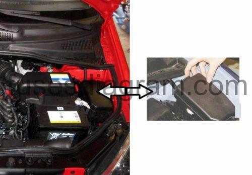
Fuse box in engine compartment.
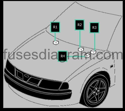
Fuse box location.
fuse box layout.
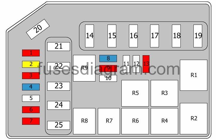
legend.
| Fuse | Amps | Circuits protected |
|---|---|---|
| 1 | 10A | Engine control unit |
| 2 | 20A | Engine control unit |
| 3 | 10A | Immobiliser control unit Oxygen sensor Brake light switch |
| 4 | 15A | Throttle actuator Camshaft position sensor PTC heater relay Glow plug relay Exhaust gas recirculation actuator |
| 5 | not used | |
| 6 | 10A | Air-conditioning relay PTC heater relay |
| 7 | 10A | Horn relay |
| 8 | 15A | Fuel pump |
| 9 | 10A | Engine control unit Or Not used |
| 10 | ||
| 11 | ||
| 12 | 25A | 12V socket Cigarette lighter |
| 13 | 10A | ABS/ESP control unit Multi-purpose check connector |
| 14 | 50A | Demister relay Tail light(s) relay Front fog light relay Power connector |
| 15 | 30A | Cooling fan relay No. 1 Cooling fan relay No. 2 |
| 16 | 30A | Fuel filter relay |
| 17 | 30A | Engine control relay Alternator Fuel pump Engine control unit |
| 18 | 30A | Ignition switch |
| 19 | 30A | Main relay Ignition switch |
| 20 | 120A | Alternator (100A also used) |
| 21 | 20A | ABS/ESP control unit Multi-purpose check connector |
| 22 | 40A | ABS/ESP control unit Multi-purpose check connector |
| 23 | 30A | Blower relay |
| 24 | 30A | Power window relay |
| 25 | 50A | Electronic power steering (EPS) |
| R1 | Main relay | |
| R2 | Blower relay | |
| R3 | Cooling fan relay No. 2 | |
| R4 | Cooling fan relay No. 1 | |
| R5 | Starter relay | |
| R6 | Air-conditioning relay | |
| R7 | Horn relay | |
| R8 | Fuel pump relay | |
| R9 | Alarm relay |
Additional fuse box in engine compartment.
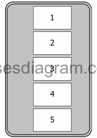
Fuse 1 – Glow plug relay (80.0 A)
Fuse 2 – PTC heater (50.0 A)
Fuse 3 – PTC heater (60.0 A)
Fuse 4 – PTC heater (50.0 A)
Fuse 5 – Electronic power steering (80.0 A)
Additional relay in engine compartment.
Relay R1 – Glow plug relay
Relay R2 – Heater relay
Relay R3 – Additional heater relay
Relay R4 – Fuel filter heater relay