For the Hyundai Accent (Hyundai Brio, Hyundai Avega, Hyundai Verna, Dodge Attitude, ) 2006, 2007, 2008, 2009, 2010, 2011 model year.
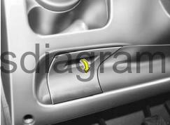
Fuse box in passenger compartment.
The fuse box will be found low on the dashboard on the driver’s side.
fuse box diagram.
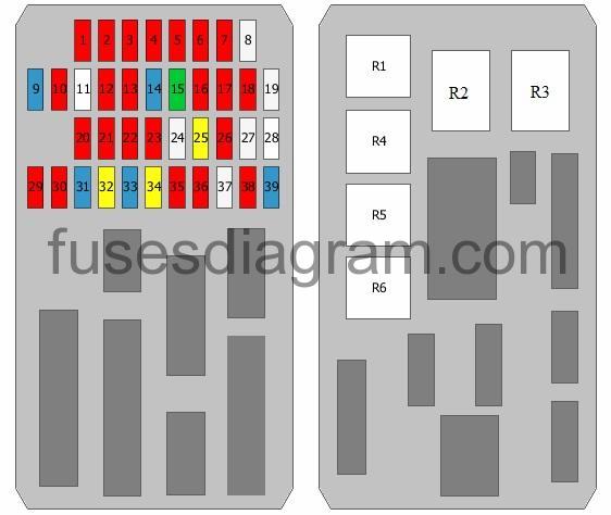
legend.
| Fuse | Amps | Circuits protected |
|---|---|---|
| 1 | 10A | Starter relay Relay box in passenger compartment, relay R1 (2010-) |
| 2 | 10A | Instrument cluster |
| 3 | 10A | Hazard warning switch |
| 4 | 10A | Hazard warning light relay (-2009) Hazard warning switch |
Relay box in passenger compartment, relay R3 (2010-)
5
10A
Rear right combination light
Number plate light(s)
Right headlight
Connector
6
10A
Rear left combination light
Number plate light(s)
Left headlight
Daylight running system control unit (-2009)
7
10A
Engine control unit
Exterior mirror (-2009)
Folding mirror (-2009)
Powertrain control unit (PCM)
Switch, rear demister
8
25A
Driver’s power window switch
Switch, rear left power window(s)
9
15A
Audio
10
10A
Luggage compartment light
Interior light
Vanity light
Digital clock
Overhead console
Air-conditioning control unit
Instrument cluster
Warning buzzer
Door open
Body control unit (BCM)
11
Spare fuse
12
10A
Airbag switch (-2009)
Not used (2010-)
13
10A
Overdrive main switch
Vehicle speed sensor
TCM (2010-)
Pulse generator (2010-)
14
15A
SRS control unit
15
30A
Body control unit (BCM)
Rear demister
16
10A
Headlight levelling switch
Headlight levelling actuator(s)
Diesel fuel heater relay
Front fog light relay
Demister (2010-)
Power window relay (2010-)
17
10A
Rear combination light(s)
Rear fog light switch
Body control unit (BCM)
18
10A
Folding mirror (-2009)
Exterior mirror
Digital clock
Audio
19
25A
Driver’s power window switch
Power window switch, front passenger
Switch, rear right power window(s)
20
10A
Body control unit (BCM)
Instrument cluster
Generator
Daylight running system control unit (-2009)
Demister (2010-)
21
10A
Engine control unit
Powertrain control unit (PCM)
EPS control unit
Or
Engine control unit
Powertrain control unit (PCM)
EPS control unit
Mass airflow meter
Fuel filter warning switch
22
10A
Daylight running system control unit
23
10A
Front fog light switch
Front left fog light
Front right fog light
Body control unit (BCM)
24
25A
Amplifier
25
20A
Driver’s seat heater switch
Heated front seat(s) switch
26
10A
Exterior mirror (-2009)
Folding mirror (-2009)
not used (2010-)
27
25A
Cigarette lighter
Power outlet
28
Spare fuse
29
10A
Rear light switch
Or
Rear light switch
Transaxle range switch
30
10A
Electronic stability program (ESP) switch
Steering angle sensor
ABS control unit
ESP control unit
Multi-purpose check connector
31
15A
Ignition coils 1 – 4
Condenser
32
20A
Door lock actuator, front left
Door lock actuator, front right
Door lock actuator, rear left
Door lock actuator, rear right
Body control unit (BCM)
Driver’s power window switch
Rear-door lock actuator
33
15A
Data link connector
Brake light switch
Power window relay
Multi-purpose check connector
34
20A
Sunroof motor
35
10A
Right headlight
Instrument cluster
Daylight running system control unit
36
10A
Humidity sender
In-car temperature sensor
Air-conditioning control unit
Body control unit (BCM)
Blower relay
Sunroof motor
Or
Humidity sender
In-car temperature sensor
Air-conditioning control unit
Body control unit (BCM)
Blower relay
Sunroof motor
PTC heater, relay 2
PTC heater, relay 3
37
25A
Front wiper motor
Multifunction switch
38
10A
Left headlight
39
15A
Multifunction switch
Rear wiper motor
R1
Front fog light relay
R2
Power window relay
R3
Rear heater relay
R4
Rear fog light relay
R5
Door unlock relay
R6
Door unlock relay
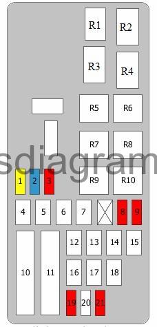
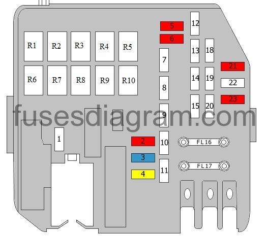
Fuse box in engine compartment.
fuse box diagram (-2009).
| Fuse | Amps | Circuits protected |
|---|---|---|
| 1 | 20A | Engine control unit Powertrain control unit (PCM) |
| 2 | 15A | Injectors (cylinders 1 – 4) Gearbox oil cooling valve Immobiliser control unit Canister purge solenoid Idle speed actuator |
| 3 | 10A | Air-conditioning relay Radiator fan relay Condenser fan relay 1 Condenser fan relay 2 Camshaft position sensor Oxygen sensors Mass airflow meter |
| 4 | 40A | ABS control unit ESP control unit Multi-purpose check connector |
| 5 | 40A | ABS control unit ESP control unit Multi-purpose check connector |
| 6 | 30A | Fuse and relay box in passenger compartment |
| 7 | 40A | Blower motor Blower relay |
| 8 | 10A | Air-conditioning relay |
| 9 | 10A | Air-conditioning control unit |
| 10 | 80A | EPS control unit |
| 11 | 125 | Generator |
| 12 | 50A | Fuse and relay box in passenger compartment |
| 13 | 30A | Main relay Fuel pump relay |
| 14 | 30A | Condenser fan relay 1 Radiator fan relay |
| 15 | 30A | Condenser fan relay 1 |
| 16 | 30A | Ignition switch |
| 17 | 40A | Ignition switch Starter relay |
| 18 | 30A | Fuse and relay box in passenger compartment |
| 19 | 10A | Engine control unit Powertrain control unit (PCM) |
| 20 | Not used | |
| 21 | 10A | Horn relay Security alarm system relay |
| R1 | Horn relay | |
| R2 | Fuel filter heater relay | |
| R3 | Main relay | |
| R4 | Blower relay | |
| R5 | Fuel pump relay | |
| R6 | Starter relay | |
| R7 | Radiator fan relay | |
| R8 | Condenser fan relay 1 | |
| R9 | Condenser fan relay 2 | |
| R10 | Air-conditioning relay |
fuse box diagram (2010 -).
| Fuse | Amps | Circuits protected |
|---|---|---|
| 1 | Spare fuse | |
| 2 | 10A | Air-conditioning relay Radiator fan relay Condenser fan relay 1 Condenser fan relay 2 Camshaft position sensor Oxygen sensors Brake light switch |
| 3 | 15A | Injectors (cylinders 1 – 4) Gearbox oil cooling valve Immobiliser control unit Canister purge solenoid Idle speed actuator Fuel pump relay |
| 4 | 20A | Engine control unit Powertrain control unit (PCM) |
| 5 | 10A | Air-conditioning control unit |
| 6 | 10A | Air-conditioning relay |
| 7 | Spare fuse | |
| 8 | 40A | Blower relay Blower motor |
| 9 | 30A | Fuse and relay box in passenger compartment |
| 10 | 40A | ABS control unit ESP control unit Multi-purpose check connector |
| 11 | 40A | ABS control unit ESP control unit Multi-purpose check connector |
| 12 | 30A | Condenser fan relay 1 |
| 13 | 30A | Condenser fan relay 1 Radiator fan relay |
| 14 | 30A | Main relay Fuel pump relay |
| 15 | 50A | Fuse and relay box in passenger compartment |
| FL16 | 125A | Alternator |
| FL17 | 80A | EPS control unit |
| 18 | 30A | Fuse and relay box in passenger compartment |
| 19 | 40A | Starter relay Ignition switch |
| 20 | 30A | Ignition switch |
| 21 | 10A | Horn relay Relay box in passenger compartment, relay R2 |
| 22 | Not used | |
| 23 | 10A | Engine control unit Powertrain control unit (PCM) |
| R1 | Fuel filter heater relay | |
| R2 | Blower relay | |
| R3 | Starter relay | |
| R4 | Condenser fan relay 1 | |
| R5 | Air-conditioning relay | |
| R6 | Horn relay | |
| R7 | Main relay | |
| R8 | Fuel pump relay | |
| R9 | Radiator fan relay | |
| R10 | Condenser fan relay 2 |