
For the Hyundai Accent (Hyundai Pony, Hyundai Excel) 1994, 1995, 1996, 1997, 1998, 1999 model year.
Fuse box in passenger compartment.
fuse box diagram.
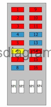
legend.
| Fuse | Amps | Circuits protected |
|---|---|---|
| 1 | 10A | Air-conditioning control |
| 2 | 10A | ABS Or ESP control unit |
| 3 | 10A | Hazard warning lights |
| 4 | 15A | Brake lights |
| 5 | 10A | Interior light(s) Audio Instrument panel Clock Transmission control unit Engine control unit |
| 6 | 20A | Heated rear windscreen |
| 7 | 10A | Rear wiper and washer |
| 8 | 15A | Front wiper(s) and washers |
| 9 | 10A | Reversing light(s) Direction indicators |
| 10 | 10A | Instrument panel Seat belt timer |
| 11 | 10A | Dashboard light, airbag |
| 12 | 15A | Airbag |
| 13 | 15A | Cigarette lighter |
| 14 | 10A | Audio Automatic transmission interlock Clock |
| 15 | 10A | Transmission control unit Fog light(s) |
| 16 | 10A | Heated seat(s) |
| SP1 | Spare fuse | |
| SP2 | Spare fuse | |
| SP3 | Spare fuse | |
| SP4 | Spare fuse |
Relay box in passenger compartment.
( -1997).

1 – Fuel pump relay II
2 – Fuel pump relay I
3 – Starter motor relay
4 –
5 –
6 –
7 – Electric window motor relay
8 – Heater blower relay
9 – Indicator relay
10 – Rear fog lamp relay
relay box in passenger compartment (1997-).
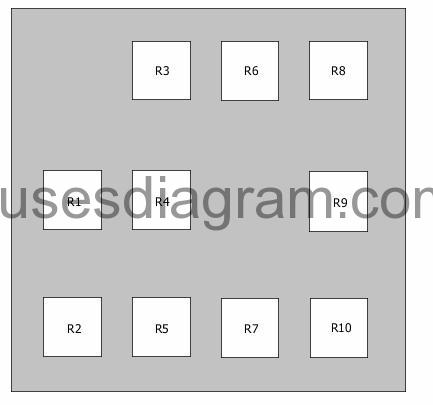
Relay R1 – Not used
Relay R2 – Blower control relay
Relay R3 – Rear fog light(s)
Relay R4 – Joint connector
Relay R5 – Power window relay
Relay R6 – Fuel pump relay, additional relay, fuel pump
Relay R7 – Flasher unit
Relay R8 – Starter relay (manual transmission)
Relay R9 – Not used
Relay R10 – Fuel pump control relay
Fuse box in engine compartment.
Location.

fuse box diagram (1997-).
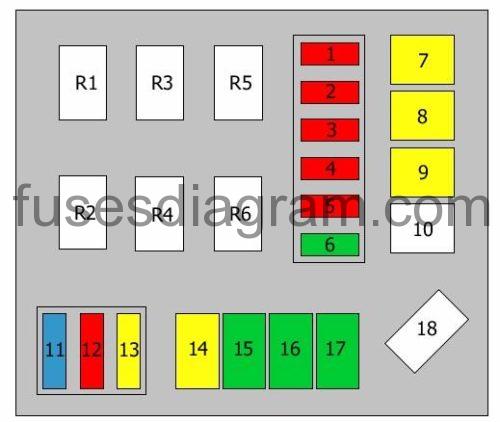
| Fuse | Amps | Circuits protected |
|---|---|---|
| 1 | 10A | Right tail light |
| 2 | 10A | Left tail light |
| 3 | 10A | Right headlight |
| 4 | 10A | Left headlight |
| 5 | 10A | Air-conditioning control |
| 6 | 30A | Blower control |
| 7 | 20A | ABS control |
| 8 | 20A | Cooling fan control |
| 9 | 20A | Power windows |
| 10 | 50A | Battery power source |
| 11 | 15A | Front fog lights |
| 12 | 10A | Horn |
| 13 | 20A | Condenser fan control |
| 14 | 20A | Engine control relay |
| 15 | 30A | Headlights Tail lights |
| 16 | 30A | ABS control |
| 17 | 30A | Ignition power source |
| 18 | 100A | Alternator |
| R1 | Cooling fan relay | |
| R2 | Horn relay | |
| R3 | Headlight relay | |
| R4 | Tail light relay | |
| R5 | Air-conditioning relay | |
| R6 | Condenser fan relay |
Fuse box layout (engine compartment).
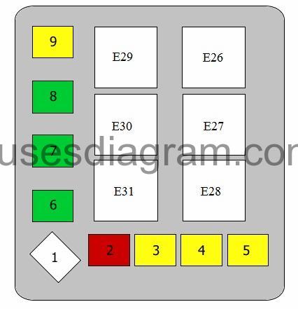
| Fuse | Amps | Circuits protected |
|---|---|---|
| 1 | 100A | Alternator |
| 2 | 50A | Battery |
| 3 | 20A | Windows |
| 4 | 20A | Engine cooling fan |
| 5 | 20A | ABS Or ESP control unit |
| 6 | 30A | Ignition switch |
| 7 | 30A | ABS Or ESP control unit |
| 8 | 30A | Exterior light(s) |
| 9 | 20A | Control unit |
| E26 | Cooling fan | |
| E27 | Headlights | |
| E28 | Air conditioning | |
| E29 | Horn | |
| E30 | Tail lights | |
| E31 | Air-conditioning cooling fan |