For the Hyundai i20 2008, 2009, 2010, 2011, 2012, 2013, 2014 model year.
Fuse box in passenger compartment.
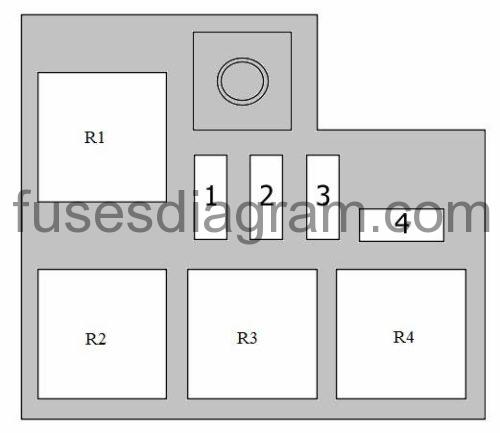
Fuse box location.

fuse box diagram.
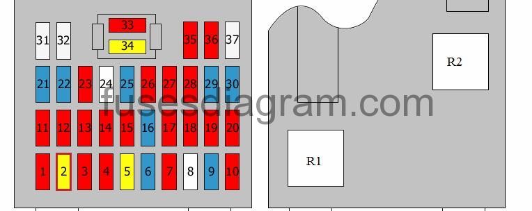
legend.
| Fuse | Amps | Circuits protected |
|---|---|---|
| 1 | 10A | Engine control unit or not used Fuse and relay box in engine compartment, relays R7, R8 |
| 2 | 20A | Sunroof control unit |
| 3 | 10A | Exterior mirror fold in/fold out feature |
| 4 | 10A | Front fog light relay |
| 5 | 20A | Tailgate unlocking relay Door lock relay Door unlock relay Deadlock relay |
| 6 | 15A | Security alarm system relay |
| 7 | 10A | Rear fog light relay |
| 8 | 25A | Not used |
| 9 | 15A | Cigarette lighter |
| 10 | 10A | Electric mirrors Audio Trip computer |
| 11 | 10A | Right headlight Rear combination light(s) Illumination |
| 12 | 10A | Daylight running system relay Number plate light Rear left combination light Left headlight |
| 13 | 10A | Hazard warning switch |
| 14 | 10A | Instrument panel |
| 15 | 10A | Transaxle range switch Rear light switch |
| 16 | 15A | Ignition coils 1 – 4 Condenser |
| 17 | 10A | ESP control unit Electronic stability program (ESP) switch Steering angle sensor ABS control unit Yaw rate sensor Fuse and relay box in engine compartment, diagnostic connector |
| 18 | 10A | Generator EPS control unit Tyre pressure monitor control unit |
| 19 | 10A | Overdrive main switch Pulse generator Vehicle speed sensor |
| 20 | 10A | Trip computer Instrument panel Body control unit (BCM) |
| 21 | 15A | Driver’s power window |
| 22 | 15A | Hazard warning switch Hazard warning light relay |
| 23 | 10A | Seat belt switch SRS control unit |
| 24 | 25A | Not used |
| 25 | 15A | Brake light switch Data link connector Power window relay |
| 26 | 10A | Fuel filter warning Mass airflow meter Engine control unit Powertrain control unit (PCM) |
| 27 | 10A | Headlight levelling switch In-car temperature sensor Body control unit (BCM) Air-conditioning control unit Sunroof control unit Headlights Fuse and relay box in engine compartment, relays R2, R3, R5 Fuse and relay box No. 1 in engine compartment, relays R2, R3 |
| 28 | 10A | Right headlight Instrument panel |
| 29 | 15A | Rear wiper motor Multifunction switch |
| 30 | 15A | Heated front seat(s) switch |
| 31 | 25A | Power windows, main switch Driver’s power window Switch, rear left power window(s) Passenger’s power window switch (right-hand drive) |
| 32 | 25A | Power windows, main switch Driver’s power window Switch, rear right power window(s) Passenger’s power window switch (left-hand drive) |
| 33 | 10A | Rear heater relay Door open Instrument panel Trip computer Tyre pressure monitor control unit Body control unit (BCM) Air-conditioning control unit Luggage compartment light Overhead console Front interior light(s) Interior light |
| 34 | 20A | Audio |
| 35 | 10A | Left headlight |
| 36 | 10A | Engine control unit Powertrain control unit (PCM) Air-conditioning control unit Electric mirrors |
| 37 | 25A | Front wiper motor Multifunction switch |
| R1 | Rear heater relay | |
| R2 | Power window relay | |
| R3 | Front fog light relay | |
| R4 | Rear fog light relay | |
| R5 | ||
| R6 | Door lock relay Door unlock relay | |
| R7 | Tailgate lock relay Tailgate unlocking relay | |
| R8 | Tail light relay | |
| R9 | Daylight running system relay | |
| R10 | Hazard warning light relay |
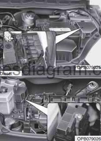
Fuse box in engine compartment.
fuse box location.
fuse box layout.
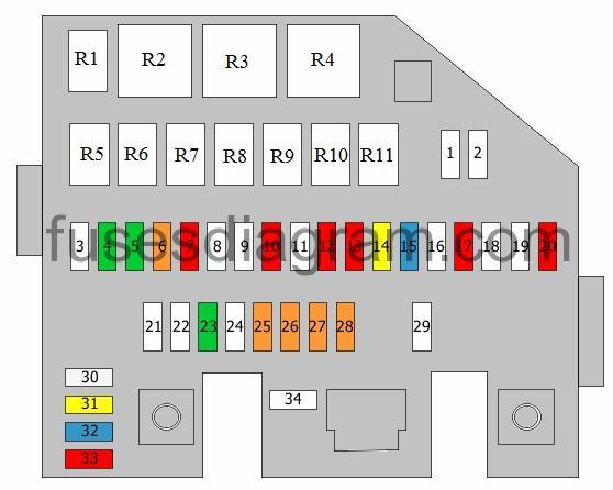
legend.
| Fuse | Amps | Circuits protected |
|---|---|---|
| 1 | not used | |
| 2 | not used | |
| 3 | 50A | Ignition switch |
| 4 | 30A | Engine control relay |
| 5 | 30A | Fuel filter heater relay |
| 6 | 40A | Ignition switch |
| 7 | 10A | Horn relay |
| 8 | not used | |
| 9 | not used | |
| 10 | 10A | Cooling fan, low-speed relay Cooling fan, high-speed relay Oxygen sensor Brake light switch Air heating |
| 11 | not used | |
| 12 | 10A | Ground |
| 13 | 10A | Fuel pressure regulator |
| 14 | 20A | Engine control unit |
| 15 | 15A | Air-conditioning relay Camshaft position sensor Variable geometry turbine (VGT) EGR Immobiliser control unit Fuse and relay box No. 1 in engine compartment, relays R1, R4 |
| 16 | not used | |
| 17 | 10A | Air-conditioning control unit |
| 18 | not used | |
| 19 | not used | |
| 20 | 10A | Air-conditioning relay |
| 21 | 50A | Fuse and relay box in passenger compartment, relay R2 Fuse and relay box in passenger compartment, fuses 21, 22 |
| 22 | 50A | Fuse and relay box in passenger compartment, relay R8 Fuse and relay box in passenger compartment, fuses 2 – 7, 25, 33, 34 |
| 23 | 30A | Cooling fan, low-speed relay Cooling fan, high-speed relay |
| 24 | 125A | Generator Fuse and relay box in engine compartment, fuses 20, 25 – 29, 34 |
| 25 | 40A | ABS control unit ESP control unit Multi-purpose check connector |
| 26 | 40A | ABS control unit ESP control unit Multi-purpose check connector |
| 27 | 40A | Rear heater relay |
| 28 | 40A | Blower relay |
| 29 | 80A | EPS control unit |
| 30 | 25A | Spare fuse |
| 31 | 20A | Spare fuse |
| 32 | 15A | Spare fuse |
| 33 | 10A | Spare fuse |
| 34 | 150A | Fuse and relay box No. 1 in engine compartment, relays R1 – R4 |
| R1 | Not used | |
| R2 | Blower relay | |
| R3 | Fuel filter heater relay | |
| R4 | Engine control relay | |
| R5 | Daylight running system relay | |
| R6 | Air-conditioning relay | |
| R7 | Starter relay | |
| R8 | Security alarm system relay | |
| R9 | Horn relay | |
| R10 | Cooling fan, low-speed relay | |
| R11 | Cooling fan, high-speed relay |
Additional fuse box in engine compartment.
| Fuse | Amps | Circuits protected |
|---|---|---|
| 1 | 50A | PTC, relay 3 |
| 2 | 50A | PTC, relay 2 |
| 3 | 50A | PTC, relay 1 |
| 4 | 80A | Glow plug relay Air heating |
| R1 | Glow plug relay | |
| R2 | PTC, relay 3 | |
| R3 | PTC, relay 2 | |
| R4 | PTC, relay 1 |