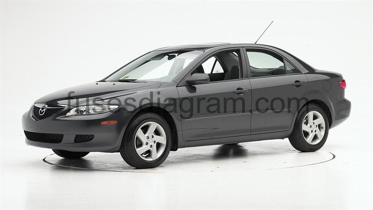
For the Mazda 6 (GG, GY) 2002, 2003, 2004, 2005, 2006, 2007, 2008 model year.
Fuse box in passenger compartment.
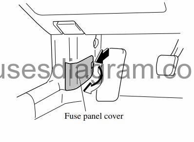
fuse box location.
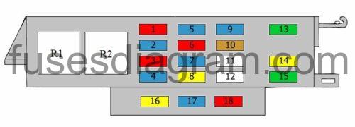
fuse box diagram.
Type 1.
legend.
| Fuse | Amps | Circuits protected |
|---|---|---|
| 1 | 10A | Air conditioning Or Body control unit (BCM) |
| 2 | 15A | Rear windscreen defroster Or Heated seats |
| 3 | 10A | Rear wiper and washer |
| 4 | 15A | Diagnostic connector Air conditioning Keyless entry receiver Illumination Audio Navigation Instrument cluster Body control unit (BCM) |
| 5 | 15A | Fuel pump relay Engine control unit Ignition coils Immobiliser Keyless entry control unit Or Fuel pump relay Fuel pump control relay Engine control unit Fuel injection relay Ignition coils Immobiliser Keyless entry control unit Or Engine control unit Immobiliser Keyless entry control unit |
| 6 | 10A | SAS |
| 7 | 15A | Instrument cluster Body control unit (BCM) Illumination Automatic light unit Daylight running system control unit Or Instrument cluster Body control unit (BCM) Illumination |
| 8 | 20A | Wash/wipe switch Automatic light unit Or Wash/wipe switch |
| 9 | 15A | Cigarette lighter |
| 10 | 5A | Cigarette lighter |
| 11 | Not used | |
| 12 | Not used | |
| 13 | ||
| 14 | 20A | |
| 15 | 30A | Body control unit (BCM) |
| 16 | Spare fuse | |
| 17 | Spare fuse | |
| 18 | Spare fuse | |
| R1 | Blower relay | |
| R2 | Fuel pump relay Or Not used |
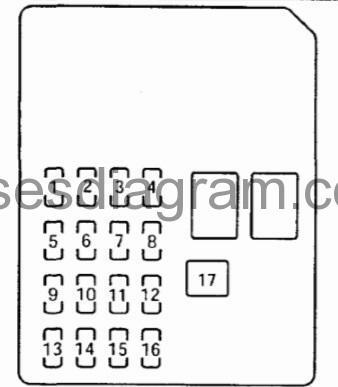
fuse box diagram.
Type 2.
DESCRIPTION | FUSE RATING | CIRCUIT PROTECTED | |
|---|---|---|---|
1 | ENGINE IG | 15A | Engine Control Unit |
2 | METER | 15A | Instrument Cluster |
3 | SEAT | 15A | Rear Window Defroster Seat Warmer* |
4 | M/DEF | 7.5A | Mirror Defroster |
5 | WIPER | 20A | Windshield Wiper & Washer |
6 | SAS | 15A | ABS Unit SAS Unit |
7 | BACK | 5 | Reverse Lights |
8 | A/C | 15A | Heater |
9 | METER ACC | 5A | Instrument Cluster |
10 | CIGAR | 15A | Cigarette Lighter |
11 | ROOM | 15A | Overhead Light |
12 | – | – | – |
13 | MIRROR | 5A | Audio System Power Control Mirror |
14 | R. CIGAR | 15A | Accessory Socket |
15 | – | – | – |
16 | D/LOCKS | 30A | Power Door Locks |
17 | – | – | – |
* Some models. Refer to wiring diagrams for any PJB related diagnosis. | |||
Fuse box in engine compartment.
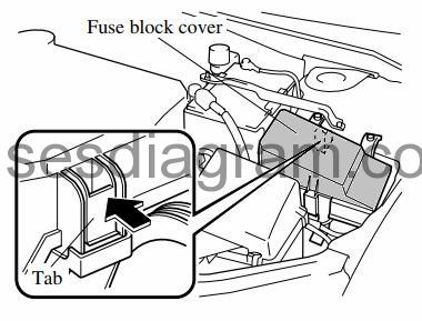
fuse box location.
fuse box layout.
legend.
| Fuse | Amps | Circuits protected |
|---|---|---|
| 1 | 30A | Cooling fan relay Or Cooling fan relay No. 2 Or Cooling fan relay No. 2 Cooling fan relay No. 3 |
| 2 | 30A | Cooling fan relay Or Cooling fan relay No. 1 |
| 3 | 60A | ABS Or ESP control unit |
| 4 | 40A | Rear windscreen defroster relay |
| 5 | 40A | Ignition switch Or Ignition switch Starter relay |
| 6 | 40A | BTN |
| 7 | 40A | Blower relay |
| 8 | 20A | Water heating system |
| 9 | 40A | Glow plug relay Or Fuel injection relay (30A also used) |
| 10 | 30A | Fuel pump relay Fuel pump control relay or not used |
| 11 | 30A | Power windows |
| 12 | 30A | Ignition switch |
| 13 | 120A | Main fuse (100A also used) |
| 14 | 15A | Front fog light relay |
| 15 | 20A | Headlight washer |
| 16 | 15A | |
| 17 | Not used | |
| 18 | 30A | Position memory control unit |
| 19 | 15A | Audio system |
| 20 | 10A | Air conditioning system |
| 21 | 20A | Fuel pump relay Main relay Or Fuel heating Or Not used |
| 22 | 7,5A | Electronic throttle control system (ETCS) relay (10A also used) or not used |
| 23 | 10A | Engine control unit Or 4WD control unit Or Transmission control unit |
| 24 | 15A | Brake pedal switch Or Horn relay (15A also used) |
| 25 | 10A | Hazard warning lights Body control unit |
| 26 | 15A | Automatic transmission relay |
| 27 | 10A | Right main beam |
| 28 | 10A | Left main beam |
| 29 | 15A | Left dipped beam |
| 30 | 15A | Right dipped beam |
| 31 | 5A | Cooling fan relay Turbo bypass solenoid or not used |
| 32 | 10A | EGR control solenoid Canister purge solenoid Mass airflow meter with air temperature sensor Inlet camshaft timing solenoid Swirl control solenoid Oxygen sensor in front of the catalytic converter Inlet manifold tuning valve Or Oxygen sensor in front of the catalytic converter Mass airflow meter with air temperature sensor Turbo pressure control solenoid (15A also used) |
| 33 | 15A | Electronic throttle control system (ETCS) relay Injectors Engine control unit Or Electronic throttle control system (ETCS) relay Engine control unit Camshaft position sensor Crankshaft position sensor Or Engine control unit (20A also used) |
| 34 | 10A | Illumination |
| 35 | 10A | Tail light(s) |
| 36 | 10A | Spare fuse |
| 37 | 15A | Spare fuse |
| 38 | 20A | Spare fuse |
| 39 | 5A | Glow plug system timer |
| 40 | 7,5A | Rear windscreen defroster |
| R1 | Powertrain control unit (PCM) relay Or Main relay | |
| R2 | Headlight relay | |
| R3 | Tail light(s) relay | |
| R4 | Front fog light relay | |
| R5 | Electronic throttle control system (ETCS) relay | |
| R6 | Cooling fan relay No. 1 | |
| R7 | Audio system relay | |
| R8 | Heated rear windscreen relay | |
| R9 | Rear fog light relay | |
| R10 | Air-conditioning relay | |
| R11 | Glow plug relay Or Automatic transmission relay Or Cooling fan relay | |
| R12 | Cooling fan relay No. 2 Or Fuel pump control relay | |
| R13 | Horn relay | |
| R14 | Cooling fan relay No. 3 Or Fuel pump relay | |
| R15 | Starter relay | |
| R16 | Cooling fan relay No. 3 Or Cooling fan relay No. 4 Or Fuel injection relay |

