
For the Mazda Tribute (EP) 2000, 2001, 2002, 2003, 2004, 2005, 2006, 2007 model year.
Fuse box in passenger compartment.
fuse box location.
The fuse panel is located below and to the left of the steering wheel by the brake pedal. Remove the panel cover to access the fuses.
fuse box diagram.
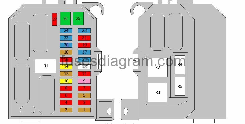
legend.
| Fuse | Amps | Circuits protected |
|---|---|---|
| 1 | 5A | Not used |
| 2 | 5A | Switch module Heated rear windscreen switch |
| 3 | 10A | Rear wash/wipe system Body control unit |
| 4 | 10A | 4WD control system Instrument panel |
| 5 | 5A | Supplemental restraint system (SRS) Airbag sensor Speed control unit ABS test connector |
| 6 | 10A | Light control switch Reversing lights |
| 7 | 10A | Supplemental restraint system (SRS) Security control unit |
| 8 | 10A | Instrument panel Body control unit Mirror switch |
| 9 | 3A | Powertrain control unit (PCM) Air-conditioning compressor clutch relay Cooling fan, low-speed relay Cooling fan, medium-speed relay Cooling fan, high-speed relay 1 |
| 10 | 20A | Windscreen wiper motor Wash/wipe switch |
| 11 | 10A | Accessory time delay relay Ignition switch |
| 12 | 5A | Clock Audio system |
| 13 | Not used | |
| 14 | 20A | Front cigarette lighter |
| 15 | 15A | Parking light relay |
| 16 | 10A | Shift interlock solenoid Instrument panel Body control unit |
| 17 | 15A | Roof control panel: sliding roof |
| 18 | 15A | Instrument panel Audio system Fog light switch |
| 19 | 10A | Subwoofer system |
| 20 | 15A | Electronic flasher module |
| 21 | 10A | Trailer connector socket |
| 22 | 15A | Rear fog light relay |
| 23 | 15A | Horn relay |
| 24 | 15A | Brake pedal switch Deactivator switch |
| 25 | 30A | Power window switches Door lock switches |
| 26 | 30A | Body control unit Electric driver’s seat 4WD relay |
| 27 | 10A | Clock Body control unit Instrument panel Audio system Antenna Data link connector |
| R1 | Accessory relay | |
| R2 | Accessory time delay relay | |
| R3 | Ignition relay | |
| R4 | Horn relay | |
| R5 | Parking light relay |
Fuse box in engine compartment.
fuse box location.

fuse box layout.
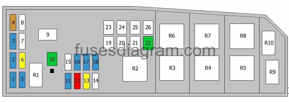
legend.
| Fuse | Amps | Circuits protected |
|---|---|---|
| 1 | 15A | |
| 2 | 15A | Left headlights |
| 3 | 15A | Right headlights Right direction indicator |
| 4 | 5A | Powertrain control unit (PCM) |
| 5 | 15A | Heated oxygen sensor Evaporative canister purge solenoid(s) |
| 6 | 20A | Fuel pump relay Additional relay, fuel pump |
| 7 | Starter relay diode | |
| 8 | Air-conditioning diode | |
| 9 | 120A | Fuse box in engine compartment, fuses 13, 14, 16 – 18, 22, 23 Alternator |
| 10 | 30A | Powertrain control unit (PCM) relay Fuse box in engine compartment, fuse 4 |
| 11 | 15A | Alternator |
| 12 | 10A | Headlight levelling |
| 13 | 20A | Fog light relay |
| 14 | 25A | ABS control unit ABS test connector |
| 15 | Not used | |
| 16 | 15A | Power point Hand-wash reservoir supply |
| 17 | 15A | Air-conditioning compressor clutch relay |
| 18 | 15A | Rear power point |
| 19 | 40A | Starter relay Ignition relay Fuse box in passenger compartment, fuse 11 |
| 20 | 40A | Accessory relay Accessory time delay relay Fuse box in passenger compartment, fuses 15, 19, 20 |
| 21 | 40A | Fuse box in passenger compartment, fuses 22 – 24, 26, 27 |
| 22 | 30A | Heated rear windscreen relay |
| 23 | 40A | Blower motor relay |
| 24 | 60A | ABS control unit ABS test connector |
| 25 | 40A | Cooling fan, low-speed relay Cooling fan, medium-speed relay |
| 26 | 40A | Cooling fan, high-speed relay 1 |
| R1 | Headlight relay | |
| R2 | Powertrain control unit (PCM) relay | |
| R3 | Fuel pump relay Additional relay, fuel pump | |
| R4 | Cooling fan, high-speed relay 1 | |
| R5 | Starter relay | |
| R6 | Cooling fan, low-speed relay | |
| R7 | Heated rear windscreen relay | |
| R8 | Cooling fan, medium-speed relay | |
| R9 | Fog light relay | |
| R10 | Air-conditioning compressor clutch relay |