
For the Mazda 6 (GH) 2008, 2009, 2010, 2011, 2012 model year.
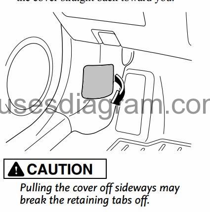
Fuse box in passenger compartment.
fuse box location.
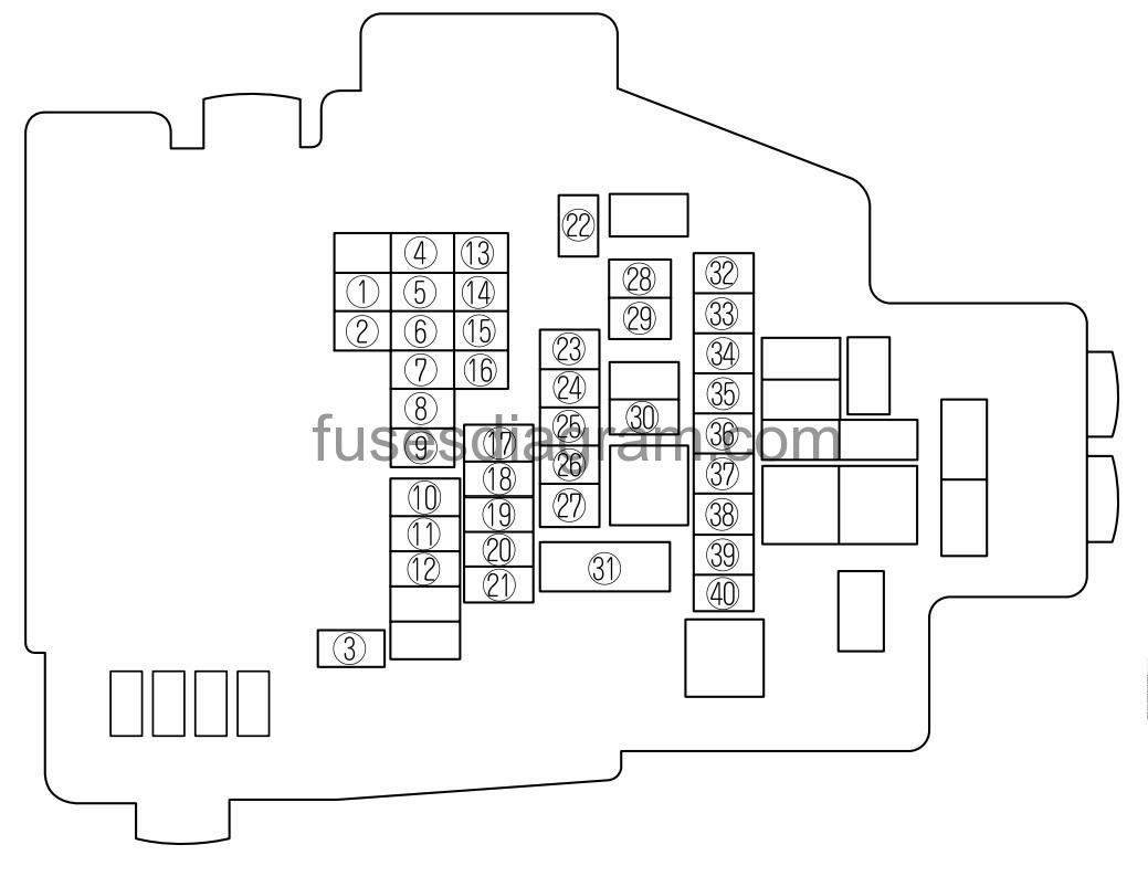
fuse box diagram.
type 1.
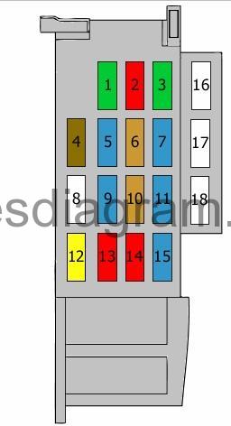
legend.
| Fuse | Amps | Circuits protected |
|---|---|---|
| 1 | 30A | Power windows |
| 2 | 10A | Automatic headlight levelling |
| 3 | 30A | Body control unit (BCM) Central locking |
| 4 | 7,5A | Body control unit (BCM) Illumination |
| 5 | 15A | Cigarette lighter or not used |
| 6 | 5A | Shift interlock solenoid Electric mirrors Keyless entry control unit Accessory socket Audio system Bluetooth system Information display |
| 7 | 15A | Accessory socket Power outlet |
| 8 | Not used | |
| 9 | 15A | Cooling system Fuel system Control system Electronic power steering (EPS) Keyless entry control unit |
| 10 | 5A | Airbag module |
| 11 | 15A | Airbag module Immobiliser Keyless entry control unit Automatic headlight levelling Instrument cluster Information display Parking sensor Rear compartment monitor control unit Body control unit (BCM) |
| 12 | 20A | Keyless entry control unit Windscreen wiper and washer switch Body control unit (BCM) |
| 13 | 10A | Heating and air conditioning control unit Seat heater Body control unit (BCM) |
| 14 | 10A | Body control unit (BCM) Rear wiper |
| 15 | 15A | Data link connector Heating and air conditioning control unit Audio system Bluetooth system Instrument cluster Information display Body control unit (BCM) |
| 16 | Not used | |
| 17 | Not used | |
| 18 | Not used |
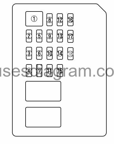
fuse box diagram.
type 2.
DESCRIPTION | FUSE RATING | PROTECTED COMPONENT | |
|---|---|---|---|
1 | P. WIND | 30 A | Power window |
2 | METER IG | 15 A | For protection of various circuits |
3 | ILLUMI | 7.5 A | BCM, Illumination |
4 | MIRROR | 5 A | Power control mirror |
5 | SAS | 5 A | Air bag, DSC |
6 | — | — | — |
7 | TNT, LOCK/SHTFT | 5 A | AT shift* |
8 | — | — | — |
9 | HEGO | 5 A | Engine control system* |
10 | A/C | 10 A | Air conditioner |
11 | P.OUTLET/CIGAR | 15 A | Power outlet |
12 | D.LOOK | 25 A | BCM, Door lock motor |
13 | ENGINE IG | 15 A | Engine control system |
14 | WIPER | 25 A | Windshield wiper and washer |
15 | ROOM | 15 A | Interior lights |
16 | SPARE | 20 A | — |
17 | SPARE | 10 A | — |
18 | SPARE | — | — |
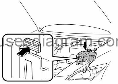
Fuse box in engine compartment.
fuse box location.
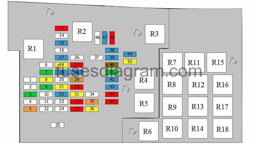
fuse box layout.
type 1.
legend.
| Fuse | Amps | Circuits protected |
|---|---|---|
| 1 | 40A | Heating and air conditioning control unit |
| 2 | Not used | |
| 3 | 30A | Power window control unit |
| 4 | 40A | Starting system Keyless entry control unit |
| 5 | 40A | Data link connector Heating and air conditioning control unit Audio system Bluetooth system Instrument cluster Information display Body control unit (BCM) |
| 6 | 60A | ABS Dynamic stability control (DSC) |
| 7 | 30A | Cooling system |
| 8 | 20A | Water heating system |
| 9 | 30A | Cooling system |
| 10 | Not used | |
| 11 | 40A | Rear windscreen defroster |
| 12 | 40A | Electric seat memory |
| 13 | 10A | Air-conditioning compressor control |
| 14 | 25A | Accessory socket |
| 15 | Not used | |
| 16 | Not used | |
| 17 | 15A | Sunroof |
| 18 | 20A | Seat heater |
| 19 | 15A | Body control unit (BCM) |
| 20 | 25A | Audio system |
| 21 | 20A | Headlight washer |
| 22 | 15A | Fog light |
| 23 | 25A | Automatic soft-close door, boot lid/tailgate |
| 24 | Not used | |
| 25 | 125A | Data link connector Cooling system Charging system Starting system ABS Dynamic stability control (DSC) Heating and air conditioning control unit Air-conditioning compressor control Water heating system Rear windscreen defroster Power window control unit Seat heater Electric seat memory Automatic soft-close door, boot lid/tailgate Sunroof Fog light Headlight washer Accessory socket Audio system Bluetooth system Keyless entry control unit Instrument cluster Information display Body control unit (BCM) |
| 26 | Not used | |
| 27 | 10A | Brake light |
| 28 | 15A | Horn |
| 29 | 5A | Control system |
| 30 | 10A | Body control unit (BCM) |
| 31 | 20A | Fuel heater Automatic transmission control unit |
| 32 | 10A | Keyless entry control unit |
| 33 | 10A | Cooling system Control system Automatic transmission control unit |
| 34 | Not used | |
| 35 | 40A | Keyless entry control unit |
| 36 | 20A | Control system |
| 37 | Not used | |
| 38 | 15A | Accessory socket |
| 39 | 15A | Accessory socket |
| 40 | 7,5A | Rear windscreen defroster |
| 41 | 30A | ABS Dynamic stability control (DSC) |
| 42 | 15A | Headlight |
| 43 | 15A | Headlight |
| 44 | 10A | Headlight |
| 45 | 10A | Headlight |
| 46 | Not used | |
| 47 | 15A | Control system |
| 48 | 10A | Control system |
| 49 | 15A | Control system |
| 50 | 20A | Fuel system |
| R1 | Air-conditioning relay | |
| R2 | Main relay | |
| R3 | Headlight relay, dipped beam | |
| R4 | Fuel pump relay | |
| R5 | Headlight relay, main beam | |
| R6 | Automatic transmission relay | |
| R7 | Starter relay | |
| R8 | Power outlet relay | |
| R9 | Cooling fan relay No. 2 | |
| R10 | Front fog light relay | |
| R11 | Horn relay | |
| R12 | Cooling fan relay No. 1 | |
| R13 | Cooling fan relay No. 4 | |
| R14 | Not used | |
| R15 | Fuel injection relay or not used | |
| R16 | Cooling fan relay No. 2 Or Cooling fan relay No. 3 | |
| R17 | Rear windscreen defroster relay | |
| R18 | Blower relay |
fuse box layout.
type 2.
DESCRIPTION | FUSE RATING | PROTECTED COMPONENT | |
|---|---|---|---|
1 | M.DEF | 10 A | Mirror Defroster* |
2 | STSIG | 5 A | Starter sig |
3 | ABS SOL | 30 A | DSC |
4 | P.WIND (P) | — | — |
5 | P.SEAT (P) | 30 A | Power seat |
6 | SUN ROOF | 15 A | Moonroof* |
7 | TAIL | 15 A | BCM, Tail lamp |
8 | P.OUTLET (R) | 15 A | Accessory sockets |
9 | AUDIO | 30 A | Audio system (Bose® Sound System-equipped model) |
10 | ABS MOTOR | 60 A | DSC |
11 | P.WIND (D) | 40 A | Power window |
12 | DEFOG | 40 A | Rear window defroster |
13 | SEAT HEAT | 20 A | Seat heat* |
14 | A/C | 10 A | Air conditioner |
15 | FOG | 15 A | Fog lights* |
16 | BLOWER 2 | — | — |
17 | FAN | 60 A | Cooling fan |
18 | P.SEAT (D) | 30 A | Power seat* |
19 | BTN | 30 A | For protection of various circuits |
20 | IGKEY2 | 40 A | Starting system |
21 | BLOWER | 40 A | Blower motor |
22 | FUEL PUMP | 25 A | Fuel pump |
23 | ENGINE2 | 15 A | Engine control system* |
24 | EGIINJ | 15 A | Injector |
25 | PCM | 10 A | Engine control system |
26 | ENGINE | 10 A*1 | Engine control system |
20 A*2 | |||
27 | IG | 20 A | For protection of various circuits* |
28 | TCM | 20 A | TCM* |
29 | ESCL | 10 A | Electronic steering lock* |
30 | IGKEY1 | 40 A | For protection of various circuits |
31 | MAIN | 125 A | For protection of all circuits |
32 | DRL | 20 A | DRL* |
33 | HAZARD | 10 A | Hazard warning flashers |
34 | ENG+B | 10 A | PCM |
35 | STOP | 10 A | Brake lights |
36 | HORN | 15 A | Horn |
37 | HEAD HI RH | 15 A | Headlight-high beam (Right)* |
38 | HEAD LO RH | 10 A | Headlight-low beam (Right) |
39 | HEAD HI LH | 15 A | Headlight-high beam (Left)* |
40 | HEAD LO LH | 10 A | Headlight-low beam (Left) |
*1 2.5-liter engine
*2 3.7-liter engine