For the Mazda 5 (CW) 2010, 2011, 2012, 2013, 2014, 2015 model year.
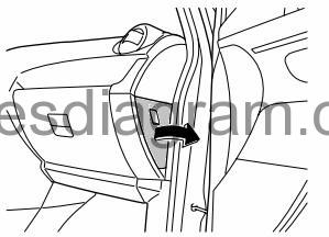
Fuse box in passenger compartment.
fuse box location.
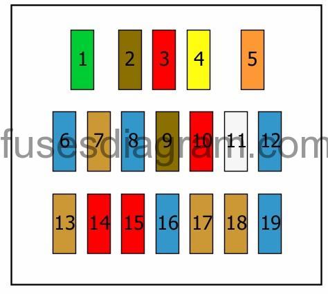
fuse box diagram.
legend.
| Fuse | Amps | Circuits protected |
|---|---|---|
| 1 | 30A | Power windows |
| 2 | 7,5A | No information is available |
| 3 | 10A | Starter system Starter relay Or Starter system Starter relay Control system Engine control unit |
| 4 | 20A | Ignition coils Or Not used |
| 5 | 40A | |
| 6 | 15A | Accessory socket Cigarette lighter |
| 7 | 5A | Shift lock |
| 8 | 15A | Accessory socket Cigarette lighter |
| 9 | 7,5A | Power windows Audio Information display |
| 10 | 10A | Manual air conditioning Automatic air conditioning Air-conditioning compressor control PTC heater Rear windscreen defroster Sunroof |
| 11 | 25A | Windscreen wash/wipe system |
| 12 | 15A | Windscreen wash/wipe system Headlight washer |
| 13 | 5A | |
| 14 | 10A | Automatic transmission control Door lock control Immobiliser Sliding door control unit Brake light Automatic headlight levelling Windscreen wash/wipe system Instrument cluster Parking sensor Information display Body control unit (BCM) |
| 15 | 10A | ABS DSC Airbag module Seat belt pretensioners |
| 16 | 15A | Heated seat(s) |
| 17 | 5A | |
| 18 | 5A | Electro-hydraulic power steering |
| 19 | 15A | Fuel system Fuel pump relay Control system Engine control unit Oxygen sensor behind the catalytic converter Fuel heater Or Control system Engine control unit Oxygen sensor behind the catalytic converter |
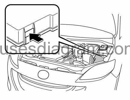
Fuse box in engine compartment.
fuse box location.
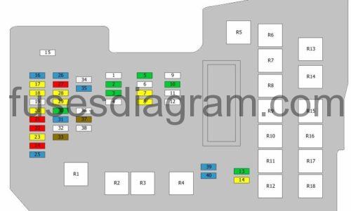
fuse box layout.
legend.
| Fuse | Amps | Circuits protected |
|---|---|---|
| 1 | 50A | Ignition switch |
| 2 | 30A | Cooling system |
| 3 | 30A | Automatic air conditioning Or Automatic air conditioning Glow plug control unit |
| 4 | 40A | Control system Main relay |
| 5 | 30A | Fuel injection relay Or Engine control unit Or Not used |
| 6 | 40A | ABS DSC Or DSC |
| 7 | 20A | Sliding door control unit |
| 8 | 20A | Automatic transmission control |
| 9 | 40A | Manual air conditioning Automatic air conditioning |
| 10 | 30A | Control system Glow plug control unit Or Not used |
| 11 | 60A | ABS DSC Air-conditioning compressor control Sliding door control unit Sunroof Headlight cleaner control relay Horn Or DSC Air-conditioning compressor control Sliding door control unit Sunroof Headlight cleaner control relay Horn |
| 12 | 40A | Starting system Starter relay Ignition switch Or Ignition switch |
| 13 | 30A | Cooling system Cooling fan motor No. 1 Or Not used |
| 14 | 20A | Sliding door control unit |
| 15 | 80A | Electro-hydraulic power steering |
| 16 | 15A | Front fog light(s) |
| 17 | 20A | Door lock |
| 18 | 20A | Power windows |
| 19 | 25A | |
| 20 | 20A | Headlight |
| 21 | 10A | Cooling system Engine control unit Cooling fan 2 relay Cooling fan 3 relay Or Automatic transmission control |
| 22 | 10A | Brake light Horn Horn relay |
| 23 | 20A | Fuel system Fuel pump relay Or Fuel heater |
| 24 | 10A | Hazard warning lights Direction indicators |
| 25 | 15A | Data link connector Shift lock Manual air conditioning Automatic air conditioning Door lock control Illumination light Audio system Instrument cluster Information display Body control unit (BCM) |
| 26 | 15A | Tail light Parking light Number plate light |
| 27 | 10A | Air-conditioning compressor control |
| 28 | 20A | ABS DSC Or DSC |
| 29 | 20A | Sunroof |
| 30 | 30A | Headlight washers |
| 31 | 15A | Horn |
| 32 | not used | |
| 33 | 7,5A | Illumination light |
| 34 | 25A | Control system Engine control unit Or Control system Camshaft position sensor |
| 35 | 15A | Control system Mass airflow meter with air temperature sensor EGR valve Canister purge solenoid Swirl control valve, solenoid Inlet manifold tuning valve Oxygen sensor in front of the catalytic converter Or Control system Fuel metering solenoid Mass airflow meter with air temperature sensor Oxygen sensor in front of the catalytic converter Turbo pressure control solenoid Exhaust gas cooler solenoid |
| 36 | not used | |
| 37 | 7,5A | Rear windscreen defroster |
| 38 | 25A | Rear windscreen defroster |
| 39 | 15A | Headlight |
| 40 | 15A | Headlight |
| R1 | Rear windscreen defroster relay | |
| R2 | TNS relay | |
| R3 | Cooling fan relay No. 1 | |
| R4 | Headlight relay | |
| R5 | Fuel heater relay Or Fuel pump relay | |
| R6 | Cooling fan relay No. 3 | |
| R7 | Rear fog light relay | |
| R8 | Cooling fan relay No. 2 | |
| R9 | Headlight washer relay | |
| R10 | Headlight relay | |
| R11 | Main relay | |
| R12 | Starter relay Or Fuel injection relay | |
| R13 | Front blower motor relay No. 1 | |
| R14 | Front blower motor relay No. 2 Or | |
| R15 | Front fog light relay | |
| R16 | Automatic transmission relay | |
| R17 | Horn relay | |
| R18 | Air-conditioning relay |
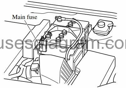
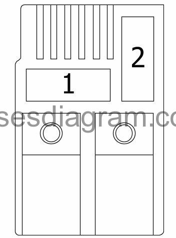
Main fuse.
| Fuse | Amps | Circuits protected |
|---|---|---|
| 1 | 250A | Charging system Alternator Starting system (450A also used) |
| 2 | 80A | Starting system Fuse and relay box in engine compartment PTC heater Or PTC heater |

