For the Mitsubishi Lancer 9 (CS) 2000, 2001, 2002, 2003, 2004, 2005, 2006, 2007, 2008 model year.
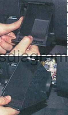
Fuse box in passenger compartment.
fuse box location.
fuse box diagram.
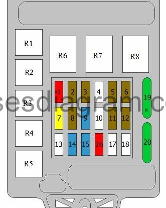
legend.
| Fuse | Amps | Circuits protected |
|---|---|---|
| 1 | 10A | Ignition coil Capacitor |
| 2 | 7,5A | ABS warning light Combination meter Electric time and alarm control system (ETACS) SRS control unit Vehicle speed sensor Brake light signal Charge warning light Steering column switches Warning light, low fuel Oil pressure sensor SRS warning light |
| 3 | 7,5A | Automatic transmission relay Combination meter Electric time and alarm control system (ETACS) SRS control unit Output shaft speed sensor Rear combination light(s) Input shaft speed sensor |
| 4 | Not used | |
| 5 | 7,5A | Air-conditioning compressor relay Air-conditioning control unit Blower relay Front control unit Relay, rear demister Relay, heated seats Heater control unit |
| 6 | 7,5A | Electric mirrors |
| 7 | 20A | Front control unit Windscreen wiper motor |
| 8 | 7,5A | Automatic transmission Engine control unit Fuel pump relay Fuel pump relay No. 2 |
| 9 | 15A | Cigarette lighter |
| 10 | Not used | |
| 11 | 7,5A | Electric mirror switch Accessory socket |
| 12 | 7,5A | ABS control unit |
| 13 | Not used | |
| 14 | 15A | Electric time and alarm control system (ETACS) control unit Rear wiper motor |
| 15 | 15A | Diagnostic system |
| 16 | 10A | Rear fog light Rear fog light warning light Rear fog light relay |
| 17 | Not used | |
| 18 | Not used | |
| 19 | 30A | Air-conditioning control unit Blower motor Heater control unit |
| 20 | 30A | Relay, rear demister |
| R1 | Fuel pump relay Additional relay, fuel pump | |
| R2 | Relay, heated seats | |
| R3 | Fuel pump relay No. 2 | |
| R4 | Accessory socket relay | |
| R5 | Rear fog light relay | |
| R6 | Power window relay | |
| R7 | Blower relay | |
| R8 | Relay, rear demister |
Fuse box in engine compartment.
fuse box location.

fuse box layout.

legend.
| Fuse | Amps | Circuits protected |
|---|---|---|
| 1 | 60A | Fuse box in passenger compartment, fuses 15, 16, 19, 20 |
| 2 | 50A | Fan control |
| 3 | 60A | ABS control unit |
| 4 | 40A | Ignition switch |
| 5 | 30A | Window switches |
| 6 | 15A | Front fog light(s) Front fog light relay Optional connector |
| 7 | 10A | Horn Horn relay |
| 8 | 20A | Camshaft position sensor EGR system Purge control valve Engine control unit Oxygen sensor Engine control relay Starter relay Fan control Fan relay Fuel injection Ignition coil relay Immobiliser control unit Automatic transmission Idle speed actuator |
| 9 | 10A | Air-conditioning compressor |
| 10 | 15A | ABS control unit Engine control unit Automatic transmission Additional brake light(s) Rear combination light(s) |
| 11 | 15A | Accessory socket |
| 12 | 7,5A | Alternator |
| 13 | 10A | Electric time and alarm control system (ETACS) control unit Direction indicators Sidelights Tail lights |
| 14 | 20A | Engine control unit Automatic transmission Automatic transmission control unit |
| 15 | 15A | Fuel pump |
| 16 | 10A | Headlights |
| 17 | 10A | Headlight(s) Main beam indicator light |
| 18 | 10A | Headlights |
| 19 | 10A | Headlight(s) Headlight levelling switch |
| 20 | 7,5A | Air-conditioning control unit Ashtray illumination Cigarette lighter illumination Combination meter Fog light Hazard warning light switch Rear combination light(s) Optional connector Headlights Headlight levelling switch Heated seat switches Heater control unit Number plate light(s) Rheostat Sidelight(s) |
| 21 | 7,5A | Combination meter Number plate light(s) Rear combination light(s) Headlight(s) |
| 22 | 10A | Combination meter Electric time and alarm control system (ETACS) control unit Front control unit Steering column control unit |
| 23 | 10A | Clock Electric time and alarm control system (ETACS) control unit Optional connector |
| 24 | Not used | |
| 25 | 20A | Heated seat switches Heated seats |
| FL26 | 120A | (100A also used) Battery Front control unit Fuse and relay box in engine compartment, fuses 1 – 15, 22 |
| FL27 | Not used | |
| R1 | Front fog light relay | |
| R2 | Horn relay | |
| R3 | Not used | |
| R4 | Not used | |
| R5 | Not used | |
| R6 | Fan control | |
| R7 | Not used | |
| R8 | Not used | |
| R9 | Not used | |
| R10 | Ignition coil relay | |
| R11 | Automatic transmission relay or not used | |
| R12 | Engine control relay | |
| R13 | Air-conditioning compressor relay Or Horn |