For the Mitsubishi Grandis (NA) 2004, 2005, 2006, 2007, 2008, 2009, 2010, 2011 model year.
Fuse box in passenger compartment.
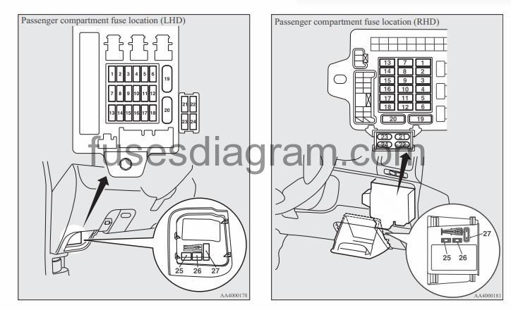
fuse box location.
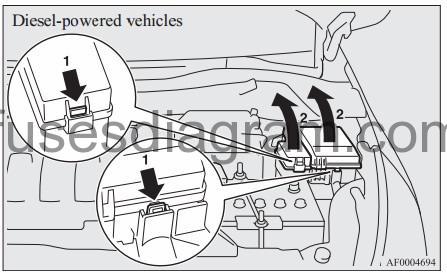
The fuse block in the passenger compartment is located behind the fuse box lid (LHD vehicles) or the personal box (RHD vehicles) in front of the driv-er’s seat at the position shown in the illustration.
fuse box diagram.
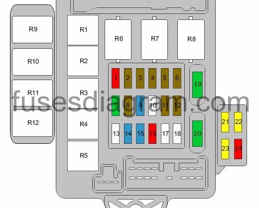
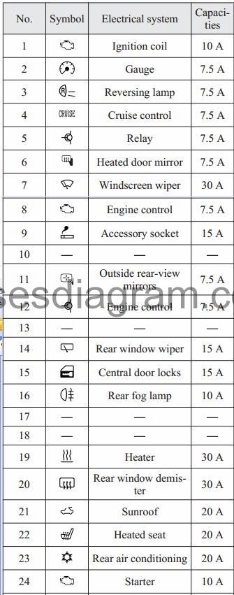
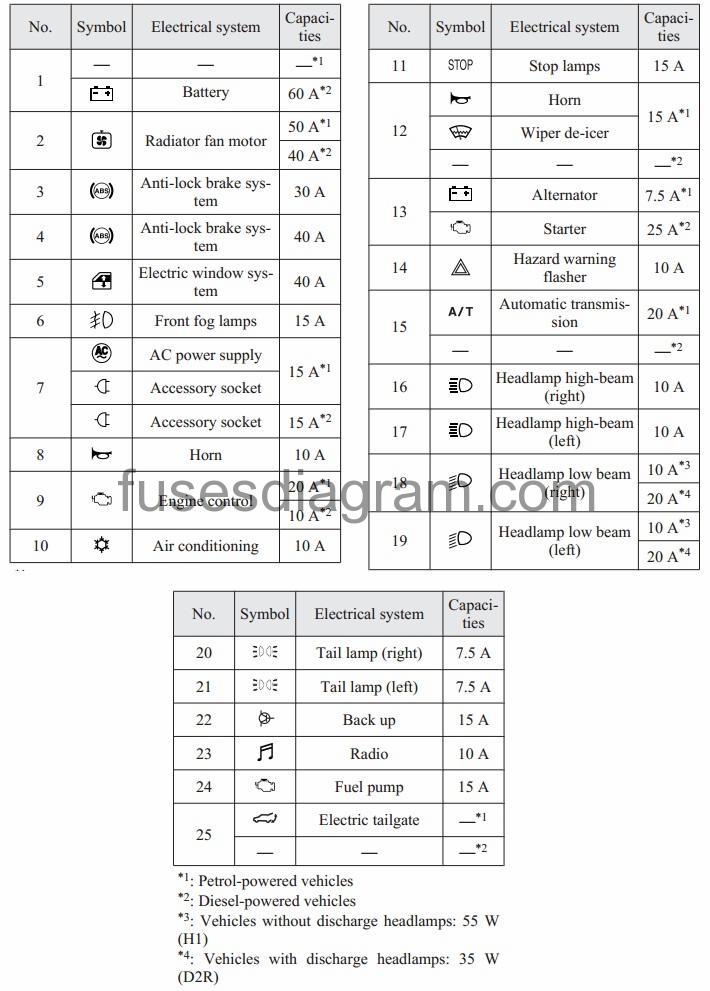
legend.
| Fuse | Amps | Circuits protected |
|---|---|---|
| 1 | 10A | Capacitor Ignition coil |
| 2 | 7,5A | ABS control unit ESP control unit Centre display Steering column switches Combination meter Engine oil level sensor relay Body control unit (BCM) Headlight levelling control unit Immobiliser control unit Multifunction display Optional connector Airbag control unit Steering wheel sensor |
| 3 | 7,5A | Automatic transmission control relay Cornering light control unit Engine control unit Body control unit (BCM) Input shaft speed sensor Output shaft speed sensor Passenger’s airbag deactivation light Airbag control unit |
| 4 | 7,5A | Not used |
| 5 | 7,5A | Air-conditioning compressor relay Air-conditioning control unit Front blower relay Front control unit Heated seat(s) relay Damping control unit PTC heater relay Rear blower relay Rear windscreen defroster relay |
| 6 | 7,5A | Door mirrors |
| 7 | 30A | Front control unit Windscreen wiper motor |
| 8 | 7,5A | Mass airflow meter Engine control unit Fuel pump relays Vehicle speed sensor |
| 9 | 15A | Accessory socket |
| 10 | Not used | |
| 11 | 7,5A | Combination meter Mirror switch |
| 12 | 7,5A | Cornering light control unit Sunroof motor |
| 13 | Not used | |
| 14 | 15A | Body control unit (BCM) Rear wiper motor |
| 15 | 15A | Diagnostic connector Body control unit (BCM) |
| 16 | 10A | Rear fog light Rear fog light relay |
| 17 | Not used | |
| 18 | Not used | |
| 19 | 30A | Front blower motor |
| 20 | 30A | Fuse and relay box in passenger compartment, fuse 6 Rear windscreen defroster |
| 21 | 20A | Sunroof motor |
| 22 | 20A | Heated seat Heated seat switch |
| 23 | 20A | Rear blower motor |
| 24 | 10A | Engine control unit |
| R1 | Fuel pump relay | |
| R2 | Rear blower relay | |
| R3 | Fuel pump relay No. 2 | |
| R4 | Rear fog light relay | |
| R5 | Heated seat(s) relay | |
| R6 | Power window relay | |
| R7 | Front blower relay | |
| R8 | Relay, rear demister | |
| R9 | PTC heater, relay 2 | |
| R10 | PTC heater, relay 1 | |
| R11 | PTC heater, relay 4 | |
| R12 | PTC heater, relay 3 |
Fuse box in engine compartment.
fuse box location.
fuse box layout.
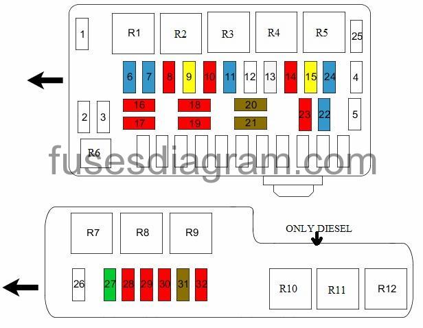
legend.
| Fuse | Amps | Circuits protected |
|---|---|---|
| 1 | 60A | Fuse and relay box in engine compartment, fuses 27 – 32 Engine control relay |
| 2 | 40A | Fuse and relay box in engine compartment, fuse 26 Condenser fan relay Radiator fan motor |
| 3 | 30A | ABS control unit ESP control unit |
| 4 | 40A | ABS control unit ESP control unit |
| 5 | 40A | Fuse and relay box in passenger compartment, fuse 21 Front control unit Power window switches |
| 6 | 15A | Front fog lights Front fog light relay |
| 7 | 15A | Accessory socket |
| 8 | 10A | Horn Horn relay |
| 9 | 20A | Engine main relay |
| 10 | 10A | Air-conditioning compressor relay |
| 11 | 15A | ABS control unit ESP control unit Engine control unit Brake light switch Tail lights |
| 12 | Not used | |
| 13 | 25A | Starter relay |
| 14 | 10A | Body control unit (BCM) |
| 15 | 20A | Automatic transmission selec |
| 16 | 10A | Headlights |
| 17 | 10A | Headlights |
| 18 | 10A | Right headlight (20A also used) |
| 19 | 10A | Left headlight Headlight levelling control unit (20A also used) |
| 20 | 7,5A | Ashtray illumination Automatic transmission gear selector illumination Combination meter Fog light switch Glovebox light Hazard warning light switch Headlight levelling switch Heated seat switch Passenger’s airbag deactivation light Dimmer Rear heater Optional connector Tail lights Traction control switch |
| 21 | 7,5A | Number plate light Dimmer Tail lights |
| 22 | 15A | Air-conditioning control unit Centre display Steering column switches Combination meter Body control unit (BCM) Front control unit Multimedia display Radio CD player Optional connector Vanity mirror(s) illumination Accessory socket relay |
| 23 | 10A | Air-conditioning control unit Centre display Body control unit Multifunction display Radio CD player Optional connector |
| 24 | 15A | Fuel pump relay Fuel gauge |
| 25 | Not used | |
| 26 | 30A | Condenser fan relay |
| 27 | 30A | Engine control unit |
| 28 | 10A | Inlet air control valve (IACV) Or Oxygen sensor |
| 29 | 10A | Condenser fan relay Fan control relay Glow plug relay Radiator fan relay Starter relay |
| 30 | 10A | Exhaust gas cooler solenoid Swirl control valve Variable geometry turbine (VGT) Vehicle speed sensor Or Emission control system |
| 31 | 7,5A | Immobiliser control unit |
| 32 | 10A | Heater blower |
| R1 | Front fog light relay | |
| R2 | Horn relay | |
| R3 | Not used | |
| R4 | Not used | |
| R5 | Accessory socket relay | |
| R6 | Engine control relay | |
| R7 | Fan control relay | |
| R8 | Radiator fan relay | |
| R9 | Glow plug relay | |
| R10 | Condenser fan relay | |
| R11 | Starter relay | |
| R12 | Air-conditioning compressor relay |
Fusible link box in engine compartment.
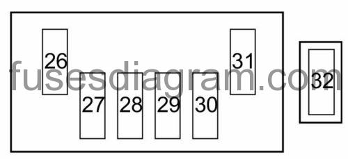
| Fuse | Amps | Circuits protected |
|---|---|---|
| 26 | 120A | Fuse and relay box in engine compartment, fuses 1 – 15, 22, 24 |
| 27 | 50A | Glow plug relay |
| 28 | 60A | Fuse and relay box in passenger compartment, fuse 22 PTC heater |
| 29 | 40A | Ignition switch |
| 30 | 80A | Fuse and relay box in passenger compartment, fuses 15 – 20, 23 |
| 31 | 175A | Fuse box in engine compartment, fusible links 26 – 30, 32 |
| 32 | 60A | PTC heater |