For Toyota Corolla 1991, 1992, 1993, 1994, 1995, 1996, 1997 model year, E100 chassis.
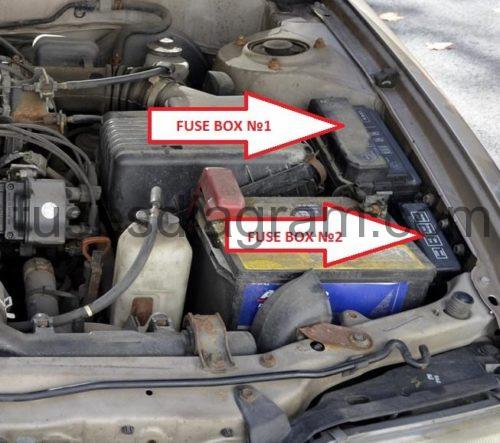
Fuse box in engine compartment.
fuse box location.
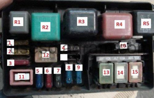
Fuse box diagram.
№1
legend.
R1 | Horn relay |
R2 | Engine coolant blower motor relay II |
R3 | Engine coolant blower motor relay I |
R4 | Headlamp relay |
R5 | Engine control module relay |
F1 | (20A) Interior lamps |
F2 | (20A) Hazard lamps, horn |
F3 | (7,5A) Idle speed control |
F4 | (7,5A) Alternator |
F5 | Spare |
F6 | Spare |
F7 | Spare |
F8 | (15A) Headlamp-right |
F9 | (15A) Headlamp-left |
F10 | (15A) Injection system, fuel heater |
F11 | (30A) Ignition switch |
F12 | (30A) Engine coolant blower motor |
F13 | (40A) Injection system |
F14 | (100A) Main circuits (injection) |
F15 | (50A) ABS |
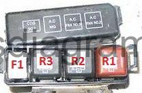
Fuse box diagram.
№2
R1 | Air conditioning condenser blower motor relay I |
R2 | Air conditioning condenser blower motor relay II |
R3 | Air conditioning compressor clutch relay |
F1 | (30A) Air conditioning condenser blower motor |
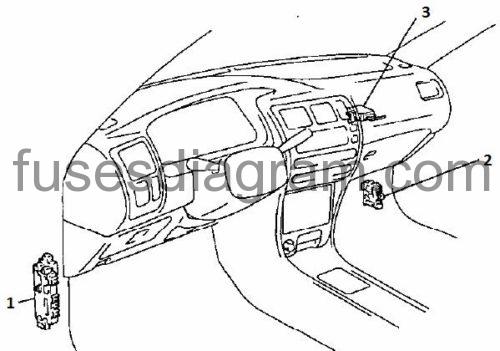
Fuse box in passenger compartment Toyota Corolla E100.
fuse box location.
The driver side fuse box (1) is located behind the driver's kick panel. The passenger side fuse box (2) is located behind passenger's kick panel.
3 – Door lock control relay.
driver side fuse box layout.
1.
1 |
|
2 | Tail lamps relay |
3 | Rear fog lamp relay |
4 | Indicator relay |
5 | Electric window motor relay |
F1 | (15A) Fog lamps |
F2 | (10A) Fuel injection, glow plug control, ignition |
F3 | (15A) Stop lamps |
F4 | (30A) Heated rear window |
F5 | (20A) Cigarette lighter, audio unit, clock, door mirror adjustment |
F6 | (10A) Rear fog lamp |
F7 | (10A) Indicators, hazard lamps |
F8 | (10A) Instrument panel, alternator, reverse lamps, electric windows, side lamps on warning buzzer, vehicle speed sensor |
F9 | (15A) Tail lamps |
F10 | (7,5A) Engine control module, idle speed control |
F11 | (15A) ABS, starter motor relay |
F12 | (20A) Windscreen wiper motor, windscreen washers, rear screen wash/wipe |
F13 | (30A) Electric windows, central locking, sunroof |
F14 | Spare |
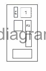
Passenger side fuse box diagram.
1 | Heater blower relay |
F1 | (15A) Air conditioning |
F2 | (40A) Heater |

