For the Volkswagen CC 2008, 2009, 2010, 2011, 2012, 2013, 2014, 2015, 2016, 2017 model year.
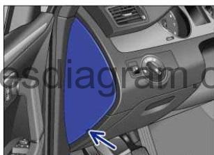
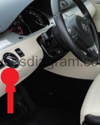
Fuse box in passenger compartment.
Fuse box is located on the driver side in the instrument panel.
fuse box diagram.
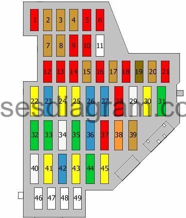
legend.
| Fuse | AMPS | Circuits Protected |
|---|---|---|
| 1 | 10A | Rear window roller blind switch Rear window roller blind motor |
| 2 | 5A | TCS/ESP button Auto-hold button ABS control unit Parking control unit |
| 3 | 5A | Light switch Brake pedal switch Oil level and temperature sensor Power steering control unit |
| 4 | 5A | Damping control unit Trailer detection control unit Cornering light and headlight range control unit Diagnostic connector |
| 5 | 10A | Switches and instruments, lighting control Headlight range control Power output control unit for the left headlight Left headlight range control motor Right headlight range control motor |
| 6 | 10A | 4WD control unit |
| 7 | 5A | Control panel control unit Data bus diagnostic interface |
| 8 | 5A | Power output control unit for the right headlight |
| 9 | 10A | Airbag control unit Passenger’s side airbag deactivation light Seat occupied recognition control unit |
| 10 | 10A | Tiptronic switch Mass airflow meter Fuel pump control unit Engine control unit Supply relay 2 terminal 30 or not used |
| 11 | 25A | Not used |
| 12 | 10A | Driver’s door control unit Passenger’s door control unit |
| 13 | 10A | Light switch Tiptronic switch Diagnostic connector |
| 14 | 10A | Alarm horn |
| 15 | 5A | Power supply control unit Interior monitor |
| 16 | 10A | Ignition lock Electronic steering column lock |
| 17 | 5A | ABS control unit Parking brake switch |
| 18 | 10A | Crankcase breather heater or not used |
| 19 | 7,5A | Adaptive cruise control unit Parking control unit Lane detection control unit Parking assistance |
| 20 | 5A | Garage door opener or not used |
| 21 | 10A | Automatic anti-dazzle rear-view mirror Heated seat switch, rear left Heated seat switch, rear right Air-conditioning high-pressure sensor Air quality sensor Blower relay Heated washer jet(s) Seat ventilation switch |
| 22 | 20A | Handbrake control unit |
| 23 | 15A | Trailer detection control unit |
| 24 | 20A | Handbrake control unit |
| 25 | 20A | Trailer detection control unit |
| 26 | 15A | Damping control unit |
| 27 | 15A | Fuel pump control unit Or Fuel pump relays Additional relay, fuel pump (20A also used) |
| 28 | 10A | Rear driver’s side door control unit Rear passenger’s door control unit Comfort system control unit |
| 29 | 25A | Heated rear seat(s) control unit |
| 30 | 20A | Sliding roof control unit |
| 31 | 30A | DC-AC converter with socket, 12V – 230V |
| 32 | 30A | Power supply control unit |
| 33 | 30A | Headlight washer relay Headlight washer pump |
| 34 | 25A | Control unit, heated front seats |
| 35 | 30A | Control unit, rear left door Control unit, rear right door |
| 36 | 15A | Driver’s seat adjustment switch Seat adjustment |
| 37 | 10A | Magnetic field sensor for the compass Rain and light sensor Climatronic control unit Air-conditioning control unit Rear-view camera control unit Remote control receiver for the auxiliary coolant heater |
| 38 | 5A | Blower relay Blower control unit Air-conditioning control unit |
| 39 | 7,5A | Multifunction switch Automatic transmission control unit Reversing light switch Mechatronic unit for the dual-clutch gearbox (15A also used) |
| 40 | 25A | Second battery charging circuit relay Washer pump |
| 41 | 20A | Cigarette lighter Rear cigarette lighter |
| 42 | 15A | 12V socket |
| 43 | 20A | Additional heater control unit |
| 44 | 30A | Driver’s door control unit Front passenger’s door control unit |
| 45 | 20A | Additional heater relay |
| 46 | Not used | |
| 47 | Not used | |
| 48 | Not used | |
| 49 | Not used |
Relay box.

relay box diagram.
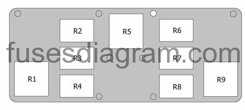
Relay R1 – Terminal 15 voltage supply relay
Relay R2 – Not used
Relay R3 – Not used
Relay R4 – Terminal 30 voltage supply relay
Relay R5 – Heated rear windscreen relay
Relay R6 – Horn relay
Relay R7 – Washer pump relay
Relay R8 – Washer pump relay 2
Relay R9 – X contact relief relay
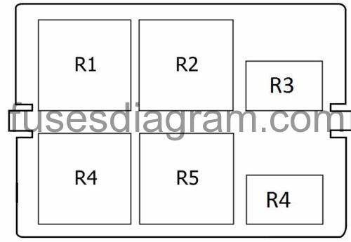
Additional fuse and relay box №1.
fuse box diagram.
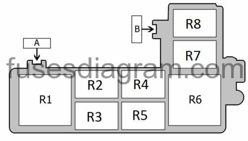
Fuse A – No information is available
Fuse B – No information is available
Relay R1 – Blower relay
Relay R2 – Fuel pump relay No. 2 or not used
Relay R3 – Additional heater relay
Relay R4 – Not used
Relay R5 – Continued coolant circulation relay Or Fuel pump relay
Relay R6 – Terminal 50 voltage supply relay or not used
Relay R7- Power supply relay or not used
Relay R8 – No information is available
Additional fuse and relay box №2.
fuse box diagram.
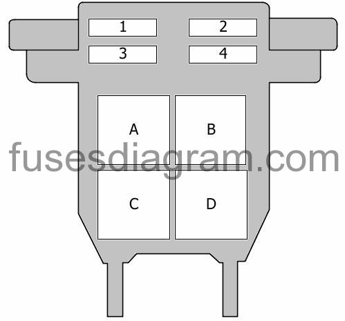
Fuse 1 – No information is available
Fuse 2 – No information is available
Fuse 3 – No information is available
Fuse 4 – No information is available
Relay A – CAN-Bus isolation relay
Relay B – Not used
Relay C – Second battery charging circuit relay
Relay D – Alarm horn relay or not used
Fuse box in engine compartment.
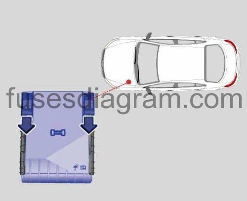
fuse box diagram (30 fuses, e-box low).

| Fuse | AMPS | Circuits Protected |
|---|---|---|
| 1 | Not used | |
| 2 | 30A | ABS control unit |
| 3 | 20A | Horns Power supply control unit |
| 4 | 25A | Trailer detection control unit |
| 5 | 5A | Power supply control unit |
| 6 | 15A | Automatic transmission control unit Mechatronic unit for the dual-clutch gearbox (15A also used) |
| 7 | 15A | Radio Information display control unit |
| 8 | 30A | Mechatronic unit for the dual-clutch gearbox |
| 9 | 5A | Electronic steering wheel control unit |
| 10 | 10A | Fuel pressure control solenoid Ignition coils or not used |
| 11 | 5A | Control panel control unit |
| 12 | 5A | Telephone TV tuner Radio |
| 13 | 10A | Main relay Engine control unit |
| 14 | 30A | Engine control unit |
| 15 | 5A | Data bus diagnostic interface |
| 16 | 10A | Coolant pump relay Exhaust gas recirculation solenoid or not used |
| 17 | 40A | Fuel pressure control solenoid Low-output heating relay |
| 18 | 5A | Low-output heating relay High-output heating relay Canister purge solenoid Camshaft timing solenoid Swirl control solenoid |
| 19 | 30A | Amplifier |
| 20 | 15A | Clutch pedal position sensor Additional relay, fuel pump Fuel pressure control solenoid Fuel pump relay |
| 21 | 20A | Additional heater control unit |
| 22 | 30A | Wiper control unit |
| 23 | 10A | Radiator fan control unit Or Radiator fan control unit Power supply relay |
| 24 | 10A | Oxygen sensor(s) or not used |
| 25 | 40A | Power supply control unit Front left sidelight(s) Right headlight, main beam Right dipped beam Left tail light(s) Right tail light(s) |
| 26 | 40A | Power supply control unit Front right sidelight(s) Left headlight, main beam Left dipped beam Left tail light Right tail light |
| 27 | 60A | Heated windscreen |
| 28 | Not used | |
| 29 | 50A | Power supply control unit |
| 30 | 50A | Power supply control unit |
| R1 | Power supply relay | |
| R2 | Main relay |
fuse box diagram (54 fuses, e-box high).

| Fuse | AMPS | Circuits Protected |
|---|---|---|
| 1 | 5A | Automatic transmission control unit Mechatronic unit for the dual-clutch gearbox (15A also used) |
| 2 | 30A | ABS control unit |
| 3 | 25A | Trailer detection control unit |
| 4 | 5A | Power supply control unit |
| 5 | 20A | Horns |
| 6 | 20A | Ignition coils or not used |
| 7 | 15A | Fuel pressure control solenoid or not used |
| 8 | 10A | Radiator fan control unit Canister purge solenoid Camshaft timing solenoid Outlet camshaft timing solenoid |
| 9 | 5A | Circulation pump relay |
| 10 | Not used | |
| 11 | 25A | Engine control unit |
| 12 | Not used | |
| 13 | Not used | |
| 14 | Not used | |
| 15 | 10A | Engine coolant circulation pump |
| 16 | 5A | Electronic steering wheel control unit |
| 17 | 5A | Control panel control unit |
| 18 | 30A | Amplifier |
| 19 | 15A | Radio Navigation control unit Information display |
| 20 | 5A | Telephone TV tuner Radio |
| 21 | Not used | |
| 22 | Not used | |
| 23 | Not used | |
| 24 | 5A | Data bus diagnostic interface |
| 25 | Not used | |
| 26 | 10A | Main relay Engine control unit |
| 27 | Not used | |
| 28 | Not used | |
| 29 | Not used | |
| 30 | 20A | Additional heater control unit |
| 31 | 30A | Wiper control unit |
| 32 | Not used | |
| 33 | 15A | Oxygen sensor in front of the catalytic converter Oxygen sensor 2 in front of the catalytic converter |
| 34 | Not used | |
| 35 | 20A | Additional heater relay |
| 36 | Not used | |
| 37 | Not used | |
| 38 | Not used | |
| 39 | Not used | |
| 40 | Not used | |
| 41 | Not used | |
| 42 | Not used | |
| 43 | Not used | |
| 44 | 10A | Fuel system diagnostic pump |
| 45 | 10A | Oxygen sensor behind the catalytic converter Oxygen sensor 2 behind the catalytic converter |
| 46 | Not used | |
| 47 | 40A | Power supply control unit Front right sidelight(s) Left headlight, main beam Left dipped beam Left tail light Right tail light |
| 48 | 40A | Power supply control unit Front left sidelight(s) Right headlight, main beam Right dipped beam Left tail light(s) Right tail light(s) |
| 49 | 50A | Power supply control unit |
| 50 | Not used | |
| 52 | Not used | |
| 52 | 60A | Heated windscreen |
| 53 | 50A | Power supply control unit |
| 54 | Not used | |
| R1 | Not used | |
| R2 | Continued coolant circulation relay | |
| R3 | Main relay, No. 2 | |
| R4 | Main relay, No. 1 |
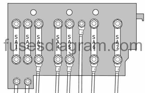
Fuse box in engine compartment (E-box High).
| Fuse | Amps | Circuits Protected |
|---|---|---|
| SA1 | 150A | Alternator (180A also used) |
| SA2 | 80A | Electromechanical power steering motor |
| SA3 | 50A | Radiator fan control unit |
| SA4 | 80A | Driver’s seat adjustment Front passenger’s seat adjustment Fuse box in passenger compartment, fuses 29 – 31 |
| SA5 | 60A | Fuse box in passenger compartment, fuses 32 – 37 |
| SA6 | Not used | |
| SA7 | 40A | ABS control unit |
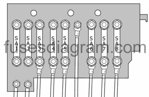
Fuse box in engine compartment (E-box Low).
| Fuse | Amps | Circuits Protected |
|---|---|---|
| SA1 | 150 | Alternator |
| SA2 | 80 | Electromechanical power steering motor |
| SA3 | 50 | Radiator fan control unit |
| SA4 | 60 | Fuse box in passenger compartment, fuses 12 – 17, 22 – 27 |
| SA5 | 80 | Fuse box in passenger compartment, fuses 29 – 31 Driver’s seat adjustment Front passenger’s seat adjustment |
| SA6 | 60 | Fuse box in passenger compartment, fuses 32 – 37 |
| SA7 | 60 | Second battery charging circuit relay Additional air heater High-output heating relay |
| SA8 | 40 | ABS control unit |
Relay box in engine compartment.
Relay R1 – Not used
Relay R2 – Glow plug relay
Relay R3 – Not used
Relay R4 – Low-output heating relay
Relay R5 – High-output heating relay
Relay R6 – Not used