This article discusses the first generation Peugeot 3008 (T84) cars produced in 2009, 2010, 2011, 2012, 2013, 2014, 2015, 2016. Gasoline engine: 1.6. and a diesel engine. Restyling, pre-restyling. You will find out where the fuses are located, in particular the fuel pump fuse, cigarette lighter fuses, fan fuses, washer fuses, license plate lights, starter, heated seats…
| The cigarette lighter fuse is located under number F9/30A – Fuse box in the passenger compartment. The fuse for the 12V socket is numbered F29/30A – Additional fuse box in the passenger compartment. |
Content:
Fuse box in the passenger compartment.
Additional fuse box in the passenger compartment.
Fuse and relay box in engine compartment.
Fuse and relay box No. 2 in the engine compartment.
Additional relays, Left hand drive.
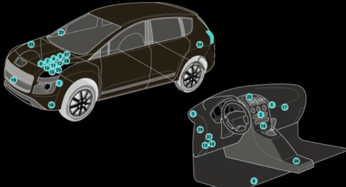
| 1 | ABS control module |
| 2 | AC control module |
| 3 | Alarm system control module |
| 4 | Battery |
| 5 | Data link connector (DLC)- in glove box |
| 6 | Electric parking brake (EPB) control module-under LH front seat |
| 7 | Engine control module (ECM) |
| 8 | Engine coolant blower motor control module-next to battery |
| 9 | Fuse box/relay plate, engine bay 1 |
| 10 | Fuse box/relay plate, engine bay 2 |
| 11 | Fuse box/relay plate, engine bay 3 |
| 12 | Fuse box/relay plate, engine bay 4 |
| 13 | Fuse box/relay plate, fascia 1 |
| 14 | Fuse box/relay plate, fascia 2 |
| 15 | Glow plug control module |
| 16 | Headlamp level control module |
| 17 | Heater blower speed resistor- behind glove box |
| 18 | Horns |
| 19 | Lane departure warning system control module |
| 20 | Multifunction control module 1-in engine bay fuse box/relay plate 1 – functions: ABS/ESP, AC/heater, engine coolant blower motor, engine management, power steering, transmission control |
| 21 | Multifunction control module 2 – in fascia fuse box/relay plate 1 – functions: ABS/ESP, AC/heater, engine management |
| 22 | Navigation system control module |
| 23 | Outside air temperature sensor-in RH door mirror |
| 24 | Parking aid control module- behind LH rear trim |
| 25 | Power steering control module |
| 26 | Supplementary restraint system (SRS) control module |
| 27 | Transmission control module (TCM) – ASM transmission |
| 28 | Transmission control module (TCM) – AT |
| 29 | Tyre pressure monitor control module |
Fuse box in the passenger compartment.
Where are the fuses located?
LHD:
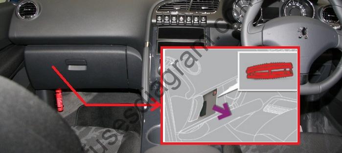
The fuse box is located in the lower part of the dashboard.
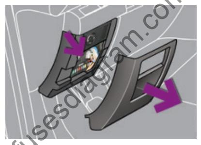
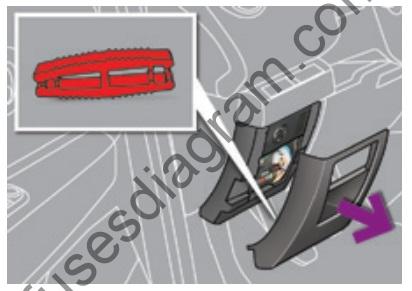
The fuse extractor pliers are installed on the back of the dashboard fuse box cover.
RHD:
fuse layout diagram in the block.
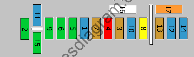
Fuse assignment.
| № | Amp | Circuits Protected |
|---|---|---|
| 1 | 15A | Back windshield wiper |
| 2 | 30A | Central locking |
| 3 | 5A | Airbag control unit |
| 4 | 10A | Electrochromatic rearview mirror Air conditioning control unit Multimedia control unit |
| 5 | 30A | Front electric windows |
| 6 | 30A | Rear electric windows |
| 7 | 5A | Interior lighting Glove box lighting 12V socket |
| 8 | 20A | Radio Multimedia display Alarm control unit Tire under-inflation detection control unit Telematics control unit |
| 9 | 30A | Front cigarette lighter Socket 12V |
| 10 | 15A | Steering wheel controls |
| 11 | 15A | Ignition switch |
| 12 | 15A | Trailer fuse box Rain and light sensor Selector handle |
| 13 | 15A | Fuse and relay box No. 1 in engine compartment Airbag control unit |
| 14 | 15A | Dashboard interface |
| 15 | 30A | Central locking |
| 16 | Shunt | |
| 17 | 40A | Heated rear window Heated mirror(s) |
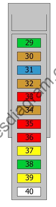
Additional fuse box in the passenger compartment.
Located next to the fuse box under the dashboard.
| № | Amp | Circuits Protected |
|---|---|---|
| 29 | 30A | 12V socket |
| 30 | 5A | Electric mirrors |
| 31 | 15A | Trailer operation |
| 32 | 5A | Semi-automatic gearbox |
| 33 | 10A | Automatic climate control Audio connection |
| 34 | 5A | Seat belt warning lamp |
| 35 | 10A | Parking assistance Hi-fi amplifier |
| 36 | 10A | Trailer control unit Driver’s door module |
| 37 | 20A | hi-fi amplifier |
| 38 | 30A | Electric driver’s seat |
| 39 | 20A | Electric sunroof |
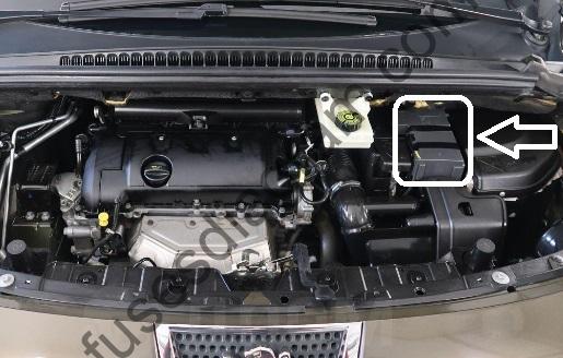
Fuse and relay box in engine compartment.
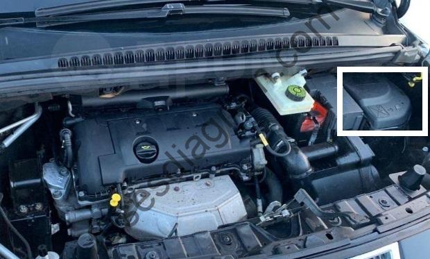
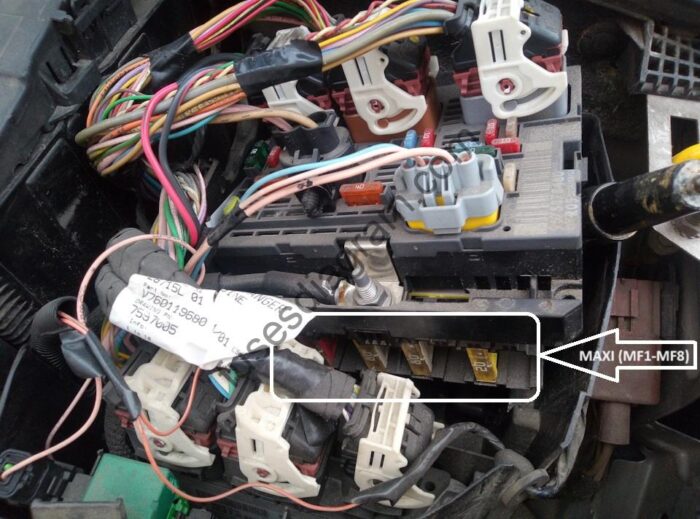
fuse layout diagram in the block.
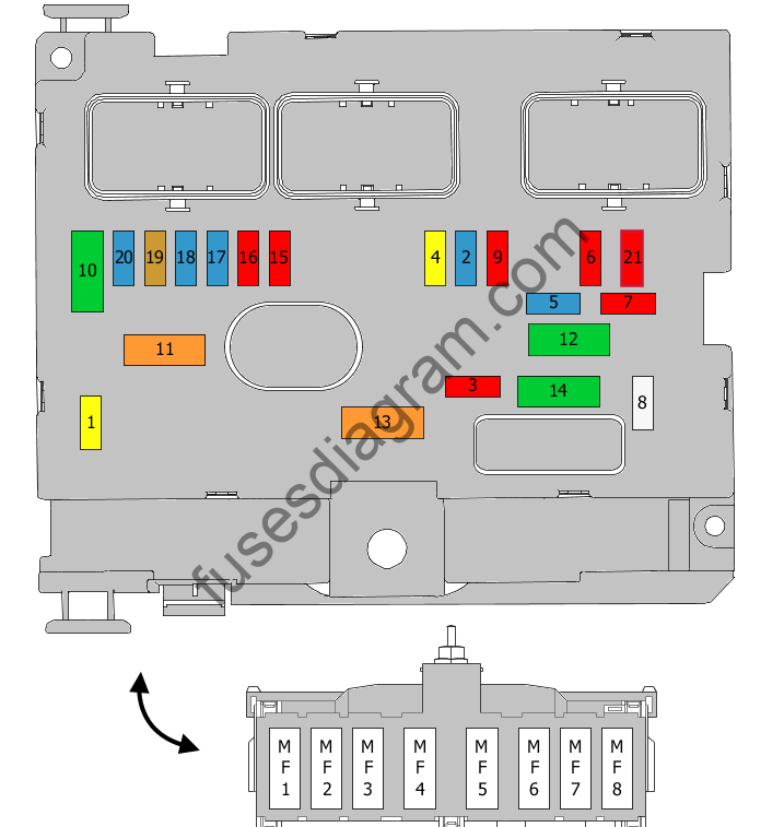
Fuse assignment.
| № | Amp | Circuits Protected |
|---|---|---|
| 1 | 20A | Main relay Power supply to engine computer, injection pump and EGR solenoid valves (2 I HDI 16V), injectors (2 I HDI 16V). or Back windshield wiper. |
| 2 | 15A | Audible warning devices |
| 3 | 10A | Windshield washers, front and rear |
| 4 | 20/10A | Active daylight indicator system |
| 5 | 15A | Fuel pump Fuel heater Purge can, turbine discharge and pressure regulation solenoid valves Turbo (1.6 liter THP), oil vapor heater (1.6 liter THP), diesel heater (1.6 liter HDI). |
| 6 | 10A | Water sensor ESP control unit ESP ASR sensor Front windows Mirror(s) Additional fuel pump Dump relay Diagnostic connector |
| 7 | 10A | Headlights Mass air flow meter Power steering computer, automatic gearbox, motor for adjusting the height of the directional headlights. |
| 8 | 25/20A | Starter relay |
| 9 | 10A | Hall sensor Clutch and brake pedal switches. |
| 10 | 30A | Water in fuel sensor Engine control unit Injection pump, diesel Engine control unit actuators (petrol: ignition coils, solenoid valves, oxygen sensors, injectors, heaters, fuel pump, electronic thermostat) ( Diesel: solenoid valves, heaters). |
| 11 | 40A | Air conditioning control |
| 12 | 30A | Front wiper control Low/high speed windshield wipers. |
| 13 | 40A | Fuses on BSI (Intelligent utility box) Integrated systems interface power supply (ignition positive). |
| 14 | 30A | Exhaust heat exchanger pump |
| 15 | 10A | Right main beam |
| 16 | 10A | Left main beam |
| 17 | 15A | Light beam managed by the left dimmer Left low beam. |
| 18 | 15A | Light beam managed by the left dimmer Right low beam. |
| 19 | 5/15A | Diesel preheating Canister purge solenoid Engine control unit Oil vapor heater (1.6 I VTi 16V), Turbo pressure regulating solenoid valve (Diesel), engine water level sensor (Diesel). |
| 20 | 15/10 | Water in fuel sensor Water sensor Electronic thermostat, variable timing solenoid valves Turbo pressure control solenoid valve (Diesel), engine water level sensor (Diesel) ). |
| 21 | 10/5A | Transfer case control unit Relaycontrol unit Fan unit relay power supply, Valvetronic relay control (1.6 I VTi 16V), Turbo cooling (1.6 I THP 16V), air flow sensor (1.6 I HDI 16V). |
| MF1 | 50A | Not used |
| MF2 | 50/30A | Trailer fuse box |
| MF3 | 50/80A | Passenger compartment fuse box |
| MF4 | 80/50A | Fuses on BSI (Intelligent utility box) |
| MF5 | 80/50A | Fuses on BSI (Intelligent utility box) |
| MF6 | 30A | Electric parking brake |
| MF7 | 30A 80A 40A | Heated front seats |
| MF8 | 20A | Headlight washer |
Allocation of fuses on the battery.
fuse layout diagram in the block.
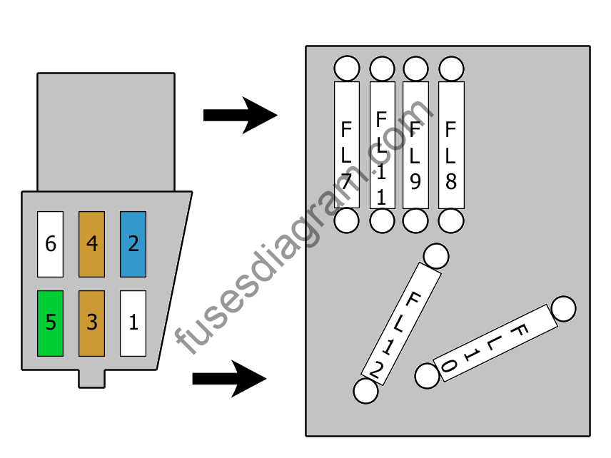
| № | Amp | Circuits Protected |
|---|---|---|
| 1 | Not used | |
| 2 | 15/5A | Stop light switch |
| 3 | 5A | Alternator Battery charging unit. |
| 4 | 25/5A | ESP control unit |
| 5 | 5/30A | ESP control unit |
| 6 | 15A | Automatic transmission control unit |
| 7 | 80A | Power steering control unit |
| 8 | 60A | Cooling |
| 9 | 30/70/80A | Preheating Engine control unit relayPreheating unit (Diesel), Valvetronic electric motor (1.6 I THP 16V). |
| 10 | 40A | ESP control unit |
| 11 | 100A | Protection and contact unit |
| 12 | 30A | Electronically controlled gearbox electric pump assembly. |
Fuse and relay box No. 2 in the engine compartment.
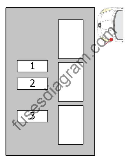
Fuse 1
Heating
Air conditioning
40.0 A
Fuse 2
Heating
Air conditioning
40.0 A
Fuse 3
Heating
Air conditioning
40.0 A
Additional relays, Left hand drive.
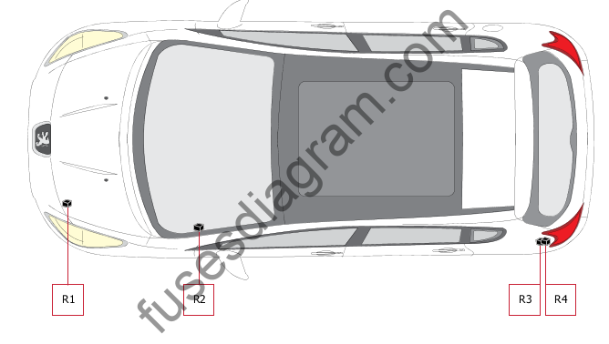
Relay R1
Main relay
Relais R2
Power outlet 12V
R3 relay
Trailer relay
Relay R4
Refrigerator relay