
For Citroen Evasion /Synergie 1994, 1995, 1996, 1997, 1998, 1999, 2000, 2001, 2002 model year.
Cigarette lighter fuse (front) – fuse box in passenger compartment – Fuse F16/20A |
MENU
Fuse box in passenger compartment.
- fuse box diagram (1995-1997)
- fuse box diagam (1997 – 07/2001)
- fuse box diagram (07/2001 – )
- relays and diagnostic connector in passenger compartment
Fuse box in engine compartment.
- fuse box diagram (1995-1997)
- fuse box diagram (1997 – 07/2001)
- fuse box diagram (07/2001 – )
- fuse box in engine compartment, main fuses, (07/2001 – )
Fuse box in passenger compartment.
fuse box location.

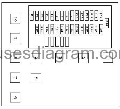
legend.
| 1 | Battery current saving relay |
| 2 | Electric window/sun-roof relay |
| 3 | Heated rear window relay |
| 4 | Heater blower relay |
| 5 | Windscreen wiper motor relay |
| 6 | – |
| 7 | Alarm system headlamp low beam relay |
| 8 | Impact central locking opening relay |
| 9 | Electric window relay, rear left or single |
| 10 | Seat heater relay |
| F1 | (10A) Audio unit |
| F2 | (5A) Interior lamp delay, instrument panel, fuel gauge, digital multifunction display, trip computer, vehicle speed sensor, engine coolant blower motor temperature switch, engine coolant low sensor, fuel/water separator sensor, speedometer, air conditioning control module |
| F3 | (15A) Spare |
| F4 | (5A) Side lamps – left, tail lamp – right, trailer socket, headlamp beam adjustment |
| F5 | (10A) Heater/air conditioning system |
| F6 | (10A) Alarm system LED, alarm system headlamp flasher relay, alarm system control module |
| F7 | (20A) Horns |
| F8 | Bridged (F15/F25) |
| F9 | (5A) Side lamps – right, tail lamp – left license plate lamp, side lamps on warning lamp |
| F10 | (30A) Spare |
| F11 | (30A) Electric windows – rear |
| F12 | (10A) Reversing lamps, alarm system horn, alarm system control module |
| F13 | (30A) Seat adjustment – passenger’s side |
| F14 | (30A) Seat adjustment – driver’s side |
| F15 | (30A) Central locking, interior lamps, interior lamp delay |
| F16 | (20A) Cigarette lighter |
| F17 | (15A) Engine coolant blower motor relay, engine coolant blower motor temperature switch, air conditioning compressor clutch relay |
| F18 | (10A) Rear fog lamps |
| F19 | (5A) Instrument panel illumination, switch illumination |
| F20 | (30A) Heater blower motor/air conditioning |
| F21 | (20A) Seat heater |
| F22 | (20A) Rear screen wiper motor, electric hinged rear windows |
| F23 | (15A) Seat heater, heated rear window, door mirror heater |
| F24 | (30A) Windscreen wiper motor, rear screen wiper motor, heated washer jets |
| F25 | (5A) Audio unit memory, clock, trip computer, central locking signal control module, alarm system |
| F26 | (30A) Hazard warning lamps |
| F27 | (30A) Heated rear window, door mirror heater |
| F28 | (15A) Stop lamps, central locking, door mirror adjustment, electric windows, electric window switch illumination, alternator warning lamp, crash control module, interior lamp delay |
| F29 | (30A) Electric windows – front, sunroof |
| F30 | (15A) Glove box lamp, side lamps on warning buzzer, indicators, interior lamps, central locking signal control module, sunroof, clock, telephone |
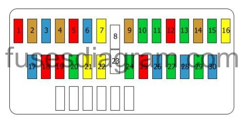
Fuse box diagram (1997 – 07/2001).

Fuse 1
Radio
10.0 A
Fuse 2
Control lights
Coolant system
Speed sensor
Water sensor, fuel filter
5.0 A
Fuse 3
Not used
Fuse 4
Front left parking light
Headlight levelling
Tail lights
5.0 A
Fuse 5
Heating
Air conditioning
Window(s)
10.0 A
Fuse 6
Heated rear windscreen
Heated seat(s)
Daylight running system
15.0 A
Fuse 7
Trailer connector socket
Horn
20.0 A
Fuse 8
Fuel system F15/F25
30.0 A
Fuse 9
Parking light(s)
Headlight washers
Tail light(s)
Number plate light(s)
5.0 A
Fuse 10
Passenger’s seat
30.0 A
Fuse 11
Rear window(s)
30.0 A
Fuse 12
Diagnostic connector
ABS
Tail lights
Crankcase breather
Automatic transmission control unit
10.0 A
Fuse 13
Driver’s seat
30.0 A
Fuse 14
Safety system
5.0 A
Fuse 15
Alarm system
Charging system
Horn
Automatic air conditioning
Manual air conditioning
30.0 A
Fuse 16
Cigarette lighter
20.0 A
Fuse 17
Cooling system
15.0 A
Fuse 18
Rear fog light(s)
10.0 A
Fuse 19
Instrument panel
10.0 A
Fuse 20
Heating
Air conditioning
30.0 A
Fuse 21
Heated seat(s)
20.0 A
Fuse 22
Rear wiper motor
Rear window(s)
20.0 A
Fuse 23
Not used
Fuse 24
Front wiper motor
30.0 A
Fuse 25
Instrument panel
Clock
Radio
Heating
Air conditioning
10.0 A
Fuse 26
Hazard warning lights
Direction indicators
15.0 A
Fuse 27
Heated rear windscreen
30.0 A
Fuse 28
Window(s)
Battery-charging control light
Brake light(s)
Cruise control
15.0 A
Fuse 29
Front window(s)
Sunroof
30.0 A
Fuse 30
Parking light(s)
Lights on
Direction indicators
Interior lights
Radio
Sunroof
Clock
15.0 A
Fuse box diagram (07/2001 – ).
Fuse 1
Radio
10.0 A
Fuse 2
Control lights
Coolant system
Speed sensor
5.0 A
Fuse 3
Brake light(s)
Cruise control
Automatic transmission
15.0 A
Fuse 4
Parking light(s)
Headlight levelling
5.0 A
Fuse 5
Heating
Air conditioning
Window(s)
10.0 A
Fuse 6
Heated rear windscreen
Heated seat(s)
Daylight running system
15.0 A
Fuse 7
Trailer connector socket
Horn
20.0 A
Fuse 8
Not used
Fuse 9
Parking light(s)
Headlight washers
5.0 A
Fuse 10
Passenger’s seat
30.0 A
Fuse 11
Rear window(s)
30.0 A
Fuse 12
Diagnostic connector
ABS
Tail lights
Crankcase breather
Automatic transmission control unit
10.0 A
Fuse 13
Driver’s seat
30.0 A
Fuse 14
Safety system
5.0 A
Fuse 15
Alarm system
Charging system
Horn
Automatic air conditioning
Manual air conditioning
30.0 A
Fuse 16
Cigarette lighter
20.0 A
Fuse 17
Cooling system
15.0 A
Fuse 18
Rear fog light(s)
10.0 A
Fuse 19
Instrument panel
10.0 A
Fuse 20
Heating
Air conditioning
30.0 A
Fuse 21
Heated seat(s)
20.0 A
Fuse 22
Rear wiper motor
Rear window(s)
20.0 A
Fuse 23
Not used
Fuse 24
Front wiper motor
30.0 A
Fuse 25
Instrument panel
Clock
Radio
Heating
Air conditioning
10.0 A
Fuse 26
Hazard warning lights
Direction indicators
15.0 A
Fuse 27
Heated rear windscreen
30.0 A
Fuse 28
Mirror(s)
Window(s)
Battery-charging control light
15.0 A
Fuse 29
Front window(s)
Sunroof
30.0 A
Fuse 30
Parking light(s)
Lights on
Direction indicators
Interior lights
Radio
Sunroof
Clock
15.0 A
Relays and diagnostic connector in passenger compartment.
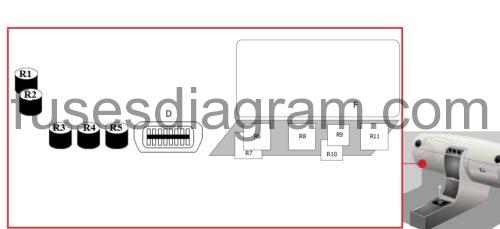
Relay R1 – Flasher relay
Relay R2 – Flasher relay
Relay R3 – No information is available
Relay R4 – Air-conditioning fan
Relay R5 – Suspension system
Relay R6 – Intermittent wash/wipe system
Relay R7 – Wash/wipe module
Relay R8 – Heated rear windscreen
Relay R9 – Windows, Sunroof
Relay R10 – Windows, Sunroof
Relay R11 – Lights on
D – Diagnostic connector
F – Fuse box
Fuse box in engine compartment.
fuse box location.

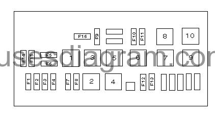
legend.
| 1 | Tachymetric relay |
| 2 | Engine coolant blower motor relay III |
| 3 | Engine coolant blower motor relay II |
| 4 | Engine coolant blower motor relay I |
| 5 | Bridged |
| 6 | Headlamp washer pump delay relay |
| 7 | Air conditioning compressor clutch relay I |
| 8 | Fog lamps relay |
| 9 | Air conditioning compressor clutch relay II |
| 10 | – |
| F1 | (20A) Spare |
| F2 | (20A) Fuel pump |
| F3 | (10A) Spare |
| F4 | (10A) Spare |
| F5 | (10A) Telephone |
| F6 | (10A) Engine control module relay |
| F7 | (10A) Spare |
| F8 | (10A) Spare |
| F9 | (25A/30A) Engine coolant blower motor |
| F10 | (30A) Fog lamps, rear fog lamps, headlamp washer |
| F11 | (30A) Spare |
| F12 | (5A) Headlamp washer |
| F13 | (15A) Oxygen sensor heater |
| F14 | (30A) ABS pump |
| F15 | (30A/40A) Heater blower motor |
| F16 | (30A/50A) Engine coolant blower motor |
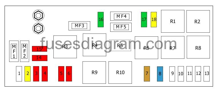
Fuse box diagram (1997 – 07/2001).
Fuse 1
No information is available
Fuse 2
Fuel pump
20.0 A
Fuse 3
Left dipped beam
10.0 A
Fuse 4
Right dipped beam
10.0 A
Fuse 5
Left main beam
10.0 A
Fuse 6
Right main beam
10.0 A
Fuse 7
Headlight washers
5.0 A
Fuse 8
Oxygen sensor
15.0 A
Fuse 9
No information is available
Fuse 10
No information is available
Fuse 11
No information is available
Fuse 12
No information is available
Fuse 13
No information is available
Fuse 14
Diagnostic connector
Telephone
Audio
10.0 A
Fuse 15
No information is available
10.0 A
Fuse 16
Cooling system (25A for XU10J2CZ engine)
30.0 A
Fuse 17
Front fog light(s)
Headlight washers
30.0 A
Fuse 18
Not used
20.0 A
Fuse MF1
No information is available
Fuse MF2
Blower
40.0 A
Fuse MF3
Cooling fan
50.0 A
Fuse MF4
No information is available
Fuse MF5
No information is available
Relay R1
Front fog lights
Relay R2
No information is available
Relay R3
No information is available
Relay R4
Cooling fan
Relay R5
Safety relay, starter motor
Relay R6
Headlight washers
Relay R7
Air conditioning
Relay R8
Cooling fan
Relay R9
Air conditioning
Relay R10
Cooling fan
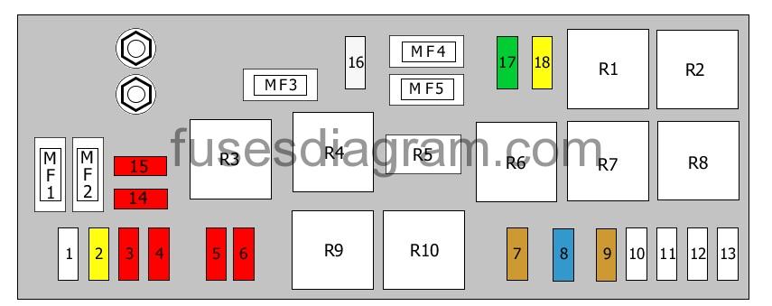
Fuse box diagram (07/2001 – ).
Fuse 1
No information is available
Fuse 2
Fuel pump
20.0 A
Fuse 3
Left dipped beam
10.0 A
Fuse 4
Right dipped beam
10.0 A
Fuse 5
Left main beam
10.0 A
Fuse 6
Right main beam
10.0 A
Fuse 7
Headlight washers
5.0 A
Fuse 8
Oxygen sensor
EGR valve
15.0 A
Fuse 9
No information is available
5.0 A
Fuse 10
No information is available
Fuse 11
No information is available
Fuse 12
No information is available
Fuse 13
No information is available
Fuse 14
Diagnostic connector
Telephone
10.0 A
Fuse 15
Injection control unit
Immobiliser
10.0 A
Fuse 16
Cooling
25.0 A
Fuse 17
Front fog light(s)
Headlight washers
30.0 A
Fuse 18
Additional heater system
20.0 A
Fuse MF1
No information is available
Fuse MF2
Heating system
Air conditioning
40.0
Fuse MF3
Cooling system
50.0 A
Fuse MF4
No information is available
Fuse MF5
No information is available
Relay R1
Front fog light(s)
Relay R2
No information is available
Relay R3
No information is available
Relay R4
Cooling fan
Relay R5
Safety relay, starter motor
Relay R6
Headlight washers
Relay R7
Air conditioning
Relay R8
Cooling fan
Relay R9
Air conditioning
Relay R10
Cooling fan
Fuse box in engine compartment, main fuses, (07/2001 – ).

Fuse MF1
Injection system double relay
20.0 A
Fuse MF2
Automatic transmission control unit
Injection system double relay
30.0 A
Fuse MF3
Air pump, EW10J4/L4 engine
30.0 A
Fuse MF4
ABS
Or
ESP control unit
60.0 A