
For Dodge Charger, Dodge Magnum 2005, 2006, 2007, 2008, 2009, 2010 model year.
Fuse box in engine compartment.
Fuse box location.
The Integrated Power Module is located in the engine compartment. This module contains fuses and relays.

fuse box diagram.
type 1.
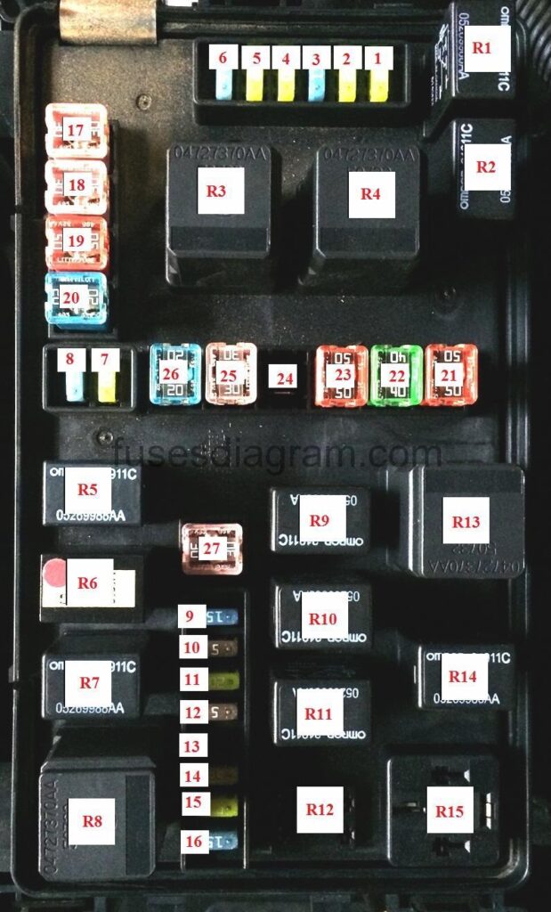
legend.
FUSE NO. | AMPS | FUNCTION |
1 | 20A | Left High Beam Headlight |
2 | 20A | Right High Beam Headlight |
3 | 15A | Adjustable Pedals |
4 | 20A | Horn |
5 | 20A | Headlight Washer – If Equipped |
6 | 15A | Front Control Module (FCM) |
7 | 20A | Fog Lamp |
8 | 15A | Park, Lamp |
9 | 15A | Non ABS Brakes |
10 | 5A | Starter |
11 | 20A | Auto Shutdown/Powertrain Control Module (PCM) |
12 | – | – |
13 | – | – |
14 | 25A | Powertrain Control Module |
15 | 20A | Injectors, Ignition Coils |
16 | 20A | Powertrain Control Module |
17 | 30A | Anti-Lock Brake System (ABS) Valves |
18 | 30A | Windshield Wiper/Washer |
19 | 50A | Radiator Fan |
20 | 20A | Starter |
21 | 50A | Anti-Lock Brake System (ABS) Pump Motor |
22 | 40A | Radiator Fan High – Low |
23 | 50A | High Intensity Lighting |
24 | – | – |
25 | 30A | Lighting Left High Beam/Right Low Beam |
26 | 20A | Transmission |
27 | 30A | Lighting Right High Beam/Right High Beam |
RELAY NO. | FUNCTION |
R1 | Horn |
R2 | A/C Clutch |
R3 | Radiator fan high |
R4 | Radiator fan high/low control |
R5 | Transmission control |
R6 | Starter |
R7 | Park, Lamp |
R8 | Auto shut down |
R9 | Wiper on/off |
R10 | Wiper high/low |
R11 | Fog lamp front |
R12 | Spare |
R13 | Radiator fan control |
R14 | Adjustable pedals (except memory) |
R15 | High intensity discharge lamp |
Fuse box diagram type 2.
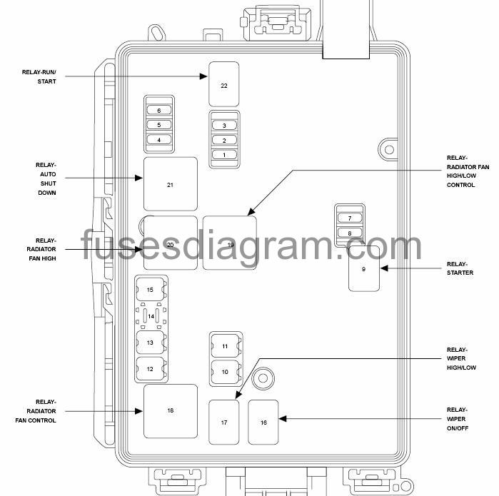
FUSE NO. | AMPS | FUNCTION |
1 | 15A | Washer Motor |
2 | 25A | Power train Control Module (PCM) |
3 | 25A | Ignition Run/Start |
4 | 25A | Alternator/EGR Solenoid |
5 | – | – |
6 | 25A | Ignition Coils/Injectors/Short Runner Valve |
7 | 25A | Headlight Washer – If Equipped |
8 | 25A | Starter |
9 | – | – |
10 | 30A | Windshield Wiper |
11 | 30A | Anti-Lock Brake System (ABS) Valves – If Equipped |
12 | 40A | Radiator Fan |
13 | 50A | Anti-Lock Brake System (ABS) Pump Motor – If Equipped |
14 | 60A | Radiator Fan |
15 | 50A | Radiator Fan |
16 | – | – |
17 | – | – |
18 | – | – |
19 | – | – |
20 | – | – |
21 | – | – |
22 | – | – |
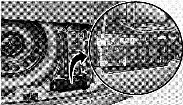
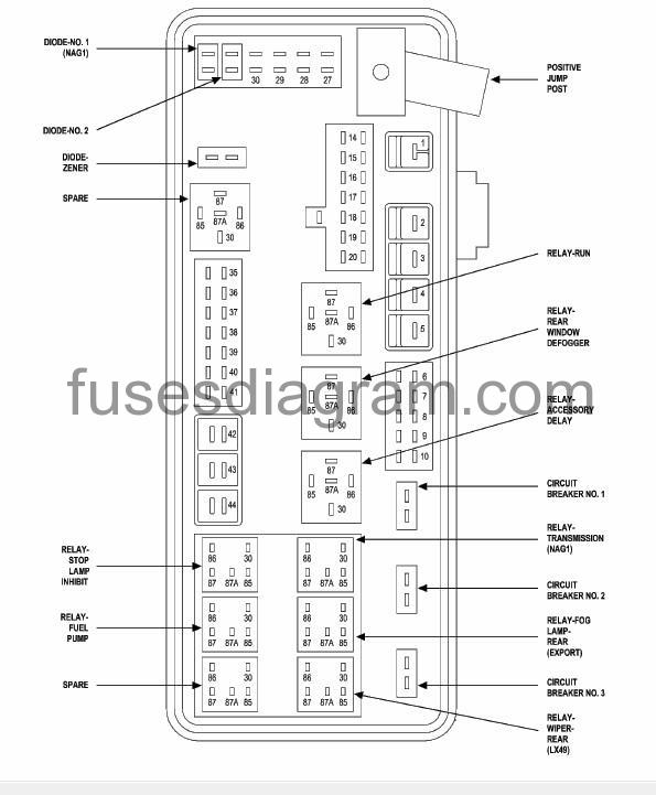
Rear Power Distribution Center.
There is also a power distribution center located in the trunk under the spare tire access panel. This center contains fuses and relays.
Opening The Access Panel.

fuse box layout.
type 1.
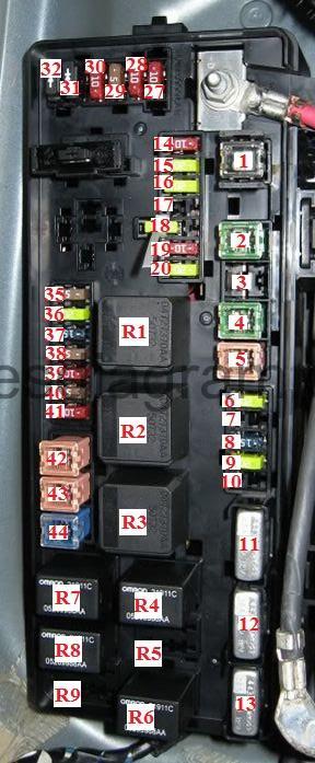
| NO. | AMPS | FUNCTION |
| 1 | 60A | Ignition Off Draw (IOD) |
| 2 | 40A | Integrated Power Module (IPM) |
| 3 | – | – |
| 4 | 40A | Integrated Power Module (IPM) |
| 5 | 30A | Heated Seats – If Equipped |
| 6 | 20A | Fuel Pump |
| 7 | 15A | Rear Heated Seats – If Equipped (300) |
| 7 | 20A | Sub Amp – If Equipped (Except 300) |
| 8 | 15A | Diagnostic Link Connector (DLC)/Wireless Control Module (WCM)/Wireless Ignition Node (WIN) |
| 9 | 20A | Power Outlet |
| 10 | – | – |
| 11 | – | Circuit breaker 1 |
| 12 | – | Circuit breaker 2 |
| 13 | – | Circuit breaker 3 |
| 14 | 10A | AC Heater Control/Cluster/Security Module – If Equipped |
| 15 | 20A | Trailer Tow Brake Module – If Equipped |
| 16 | 20A | Rear Power Outlet (Magnum) |
| 17 | 20A | Cluster |
| 18 | 20A | Selectable Power Outlet (cigarette lighter) |
| 19 | 10A | Stop Lights |
| 20 | 20A | Rear Wiper Motor (Magnum) |
| 21 | – | – |
| 22 | – | – |
| 23 | – | – |
| 24 | – | – |
| 25 | – | – |
| 26 | – | – |
| 27 | 10A | Occupant Restraint Controller (ORC) |
| 28 | 10A | Ignition Run |
| 29 | 5A | Adaptive Cruise Control (ACC) – If Equipped/Cluster/Electronic Stability Program (ESP) – If Equipped/Powertrain Control Module (PCM)/Stop Light Switch |
| 30 | 10A | Door Modules/Power Mirrors/Steering Control Module (SCM) |
| 31 | – | – |
| 32 | – | – |
| 33 | – | – |
| 34 | – | – |
| 35 | 5A | Antenna Module – If Equipped/Power Mirrors/Rain Sensor – If Equipped |
| 36 | 20A | Hands Free Phone – If Equipped/Video Monitor – If Equipped/Radio |
| 37 | 15A | Transmission |
| 38 | 10A | Analog Clock/Cargo Light/Satellite Receiver (SDARS) Video – If Equipped/Vehicle Information Module – If Equipped |
| 39 | 10A | Heated Mirrors – If Equipped |
| 40 | 5A | Auto Inside Rearview Mirror – If Equipped Heated Seats – If Equipped/Switch Bank |
| 41 | 10A | AC Heater Control/Headlights/Park Assist – If Equipped/Tire Pressure Monitoring – If Equipped |
| 42 | 30A | Front Blower Motor |
| 43 | 30A | Rear Window Defroster |
| 44 | 20A | Amplifier – If Equipped/Sunroof – If Equipped |
Relay.
| Relay NO. | FUNCTION |
| R1 | Run |
| R2 | Rear window defogger |
| R3 | Accessory delay |
| R4 | Transmission |
| R5 | Fog lamp rear |
| R6 | Wiper Rear |
| R7 | Lamp activation |
| R8 | Fuel pump |
| R9 | Heated seats rear |
Fuse box layout.
type 2.
| NO. | AMPS | FUNCTION |
| 1 | 60A | Ignition Off Draw (IOD) |
| 2 | 40A | Battery |
| 3 | – | – |
| 4 | 40A | Battery |
| 5 | 30A | Heated Seats/Steering Column |
| 6 | 20A | Fuel Pump |
| 7 | – | – |
| 8 | 15A | Ignition Start/Run – Start |
| 9 | 20A | Console Power Outlet |
| 10 | 10A | Rear Fog Lamp – If Equipped |
| 14 | 10A | Sentry Key/Remote Keyless Entry/Cluster |
| 15 | 20A | Brake Light (5.7L) |
| 16 | 20A | Power Outlet Trunk – If Equipped |
| 17 | – | – |
| 18 | 20A | Selectable Power Outlet |
| 19 | 10A | Stop Lights |
| 20 | 20A | Rear Wiper (Magnum) |
| 27 | 10A | Airbag/Airbag Control Module (ACM) |
| 28 | 10A | Curtain Airbag – If Equipped |
| 29 | 5A | Powertrain Control Module (PCM)/Sentry Key/Remote Keyless Entry/Stop Lights |
| 30 | 10A | Power Mirrors – If Equipped/Steering Control Module |
| 35 | 5A | Power Antenna/Ignition Delay/Garage Door Opener |
| 36 | 20A | Radio/Navigation |
| 37 | 15A | Transmission |
| 38 | 5A | Analog Clock/Garage Door Opener |
| 39 | 10A | Heated Mirrors |
| 40 | 5A | Power Mirror |
| 41 | 10A | Climate Control Module/Headlight Leveling – If Equipped/Rear Park Assist – If Equipped/Tire Pressure Monitoring – If Equipped |
| 42 | 30A | Automatic Temperature Control (ATC) Blower Motor |
| 43 | 30A | Rear Defroster |
| 44 | 20A | Radio Amplifier |