
For Ford B-Max (10) 2012, 2013, 2014, 2015, 2016, 2017 model year.
| Cigarette lighter fuse – fuse box in passenger compartment – Fuse F30/20A /30A |
Fuse box in passenger compartment.
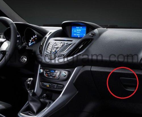
fuse box location.
Fuse box is located behind the glove box.Open the glove box and empty the contents.Press the sides inwards and swivel the glove box downward.
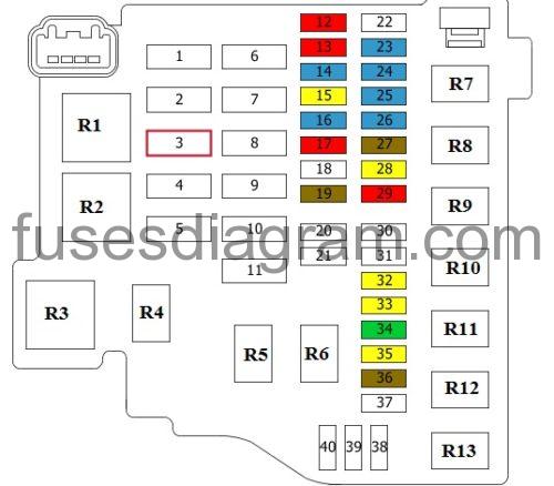
fuse box diagram (type 1).
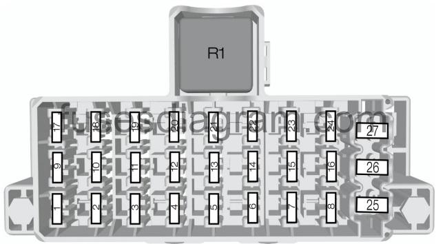
Assignment of the fuses.
| Fuse | Amps | Circuits protected | |
|---|---|---|---|
| 1 | 7.5 A | Ignition, rain sensor, heated windshield | |
| 2 | 10 A | Stop lamps | |
| 3 | 7.5 A | Reversing lamp, rearview camera | |
| 4 | 7.5 A | Headlamp leveling | |
| 5 | – | Not used | |
| 6 | 15 A | Rear window wiper | |
| 7 | 15 A | Washer pump | |
| 8 | – | Not used | |
| 9 | 15 A | Passenger’s heated seat | |
| 10 | 15 A | Driver’s heated seat | |
| 11 | – | Not used | |
| 12 | 10 A | Airbag module | |
| 13 | 10 A | Ignition, electric power assisted steering, instrument cluster, passive anti-theft system, anti-lock braking system | |
| 14 | 7.5 A | Powertrain control module, transmission selector lever, fuel pump | |
| 15 | 7.5 A | Audio system, instrument cluster | |
| 16 | 7.5 A | Heated windshield | |
| 17 | – | Not used | |
| 18 | – | Not used | |
| 19 | 15 A | Data link connector | |
| 20 | 20 A | Multi function display, clock, internal scanner, heating vents, air conditioning panel | |
| 21 | 15 A | Audio system, navigation, bluetooth | |
| 22 | 7.5 A | Instrument cluster | |
| 23 | 7.5 A | Trailer module | |
| 24 | 7.5 A | Sync module antenna | |
| 25 | – | Not used | |
| 26 | 30 A | Front wiper, left-hand side | |
| 27 | 30 A | Front wiper, right-hand side | |
| R1 | Ignition | ||
Fuse box diagram (type 2).
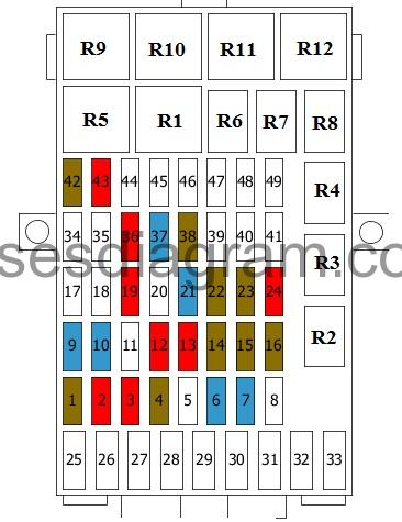
legend.
Fuse 1
Electric additional heater relay
Air-conditioning magnetic clutch relay
Front interior light
Rain sensor
Rear-view mirror dimming control
Heated windscreen relay, left side
7.5 A
Fuse 2
Brake light switch
Active Stop system relay
10.0 A
Fuse 3
Reversing light switch
Reversing light relay
10.0 A
Fuse 4
Headlight switch
Headlights
7.5 A
Fuse 5
Not used
Fuse 6
Body control unit (BCM)
15.0 A
Fuse 7
Windscreen wiper switch
15.0 A
Fuse 8
Not used
Fuse 9
Passenger’s seat
15.0 A
Fuse 10
Driver’s seat
15.0 A
Fuse 11
Not used
Fuse 12
Passenger’s airbag deactivation light
Restraint control unit (RCM)
10.0 A
Fuse 13
Body control unit (BCM)
Heating, ventilation and air conditioning control unit
Instrument panel
Power steering control unit
Immobiliser
Blower motor relay
10.0 A
Fuse 14
Accelerator pedal position sensor
Powertrain control unit (PCM)
Front fog light relay
Fuel pump relay
Or
Accelerator pedal position sensor
Transmission control unit
Powertrain control unit (PCM)
Front fog light relay
Fuel pump relay
Or
Accelerator pedal position sensor
Powertrain control unit (PCM)
Front fog light relay
7.5 A
Fuse 15
Instrument panel
Audio control unit
7.5 A
Fuse 16
Heated windscreen relay, right
7.5 A
Fuse 17
Not used
Fuse 18
Not used
Fuse 19
Data link connector (DLC)
10.0 A
Fuse 20
Not used
Fuse 21
Audio control unit
15.0 A
Fuse 22
Instrument panel
7.5 A
Fuse 23
Remote control receiver
Heating, ventilation and air conditioning control panel
Heating, ventilation and air conditioning control unit
7.5 A
Fuse 24
GPS system
10.0 A
Fuse 25
Not used
Fuse 26
Windscreen wiper motor, passenger’s side
30.0 A
Fuse 27
Windscreen wiper motor, driver’s side
30.0 A
Fuse 28
DC-DC converter
30.0 A
Fuse 29
Battery saver relay
20.0 A
Fuse 30
Auxiliary power point relay
Cigar lighter
30A/20A
Fuse 31
Not used
Fuse 32
Not used
Fuse 33
Not used
use 34
Not used
Fuse 35
Not used
Fuse 36
Data link connector (DLC)
10.0 A
Fuse 37
Ignition switch
15.0 A
Fuse 38
Alarm sensor
7.5 A
Fuse 39
Not used
Fuse 40
Not used
Fuse 41
Not used
Fuse 42
Rear-view camera system
7.5 A
Fuse 43
Active Stop system
10.0 A
Fuse 44
Not used
Fuse 45
Not used
Fuse 46
Not used
Fuse 47
Not used
Fuse 48
Not used
Fuse 49
Not used
Relay R1
Ignition relay
Relay R2
Cooling fan relay
or
Cigar lighter
Relay R3
Not used
Relay R4
Active Stop system relay
Relay R5
Not used
Relay R6
Keyless entry relay
Relay R7
Keyless entry relay
Relay R8
Battery saver relay
Relay R9
Heated windscreen relay, left side
Relay R10
Heated windscreen relay, right
Relay R11
Not used
Relay R12
Not used
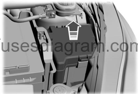
Fuse box in engine compartment.
fuse box location.
fuse box diagram.
legend.
| Fuses | Amps | Circuits protected |
|---|---|---|
| 1 | 40 A | Anti-lock braking system module |
| 1 | 30 A | Anti-lock braking system, electronic stability program module |
| 2 | 60 A | Cooling system fan high speed |
| 3 | 40 A | Cooling system fan |
| 3 | 30 A | Cooling system fan low speed |
| 4 | 30 A | Heater blower |
| 5 | 60 A | Passenger’s compartment fuse box supply (battery) |
| 6 | 30 A | Body control module |
| 7 | 60 A | Passenger’s compartment fuse box supply (ignition) |
| 8 | 60 A | Glow plugs |
| 8 | 50 A | DPS6 module |
| 9 | 40 A | Heated windshield |
| 10 | 40 A | Heated windshield |
| 11 | 30 A | Starter relay |
| 12 | 10 A | High beam left-hand relay |
| 13 | 10 A | High beam right-hand relay |
| 14 | 15 A | Run on pump |
| 15 | 20 A | Ignition coil |
| 16 | 15 A | Powertrain control module, high and low cooling fan |
| 17 | 15 A | Heated oxygen sensors (gasoline engines) |
| 17 | 20 A | Power supply module (diesel engines) |
| 18 | – | Not used |
| 19 | 7.5 A | Air condition controller |
| 20 | – | Not used |
| 21 | – | Not used |
| 22 | 15 A | Lighting control battery supply |
| 23 | 15 A | Front fog lamps |
| 24 | 15 A | Direction indicators |
| 25 | 15 A | Exterior lighting left-hand side |
| 26 | 15 A | Exterior lighting right-hand side |
| 27 | 7.5 A | Powertrain control module |
| 28 | 20 A | Anti-lock braking system, electronic stability program |
| 29 | 10 A | Air conditioning clutch |
| 30 | – | Not used |
| 31 | – | Not used |
| 32 | 20 A | Horn, battery saver, keyless vehicle module |
| 33 | 20 A | Heated rear window |
| 34 | 20 A | Fuel pump relay, diesel fuel heater |
| 35 | 15 A | Catl alarm system |
| 36 | 7.5 A | Automatic transmission controller |
| 37 | 25 A | Front door module left-hand side |
| 38 | 25 A | Front door module right-hand side |
| 39 | 25 A | Rear door module left-hand side |
| 40 | 25 A | Rear door module right-hand side |
| Relay | Circuits switched | |
| R1 | Cooling system fan | |
| R2 | Not used | |
| R3 | Powertrain control module | |
| R4 | High beam | |
| R5 | Not used | |
| R6 | Not used | |
| R7 | Engine cooling fan | |
| R8 | Starter | |
| R9 | Air conditioning clutch | |
| RIO | Front fog lamps | |
| Rll | Fuel pump, diesel fuel heater | |
| R12 | Reversing lamp | |
| R13 | Heater blower | |
Main fuse box in engine compartment.
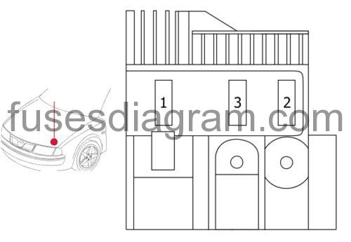
legend.
Fuse 1
Starter motor
Generator
450.0 A
Fuse 2
Power steering control unit
60.0 A
Fuse 3
Fuse and relay box in engine compartment
200.0 A
Additional relays in engine compartment.

Relay R1
Electric additional heater relay
Relay R2
Electric additional heater relay