For the Ford Taurus 2000, 2001, 2002, 2003, 2004, 2005, 2006, 2007 model year.
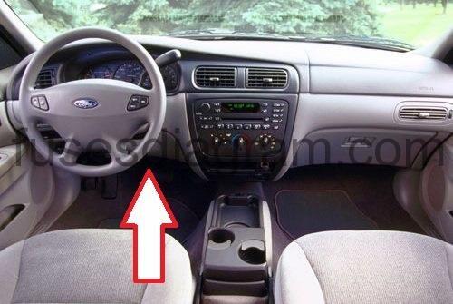
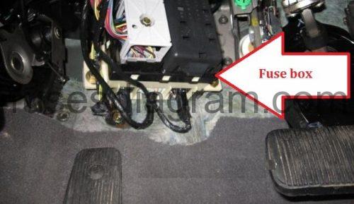
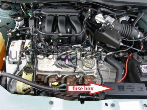
Fuse box located.
Passenger compartment fuse panel.
The fuse panel is located below and to the left of the steering wheel by the brake pedal.
Remove the panel cover to access the fuses. To remove a fuse use the fuse puller tool provided on the fuse panel cover.
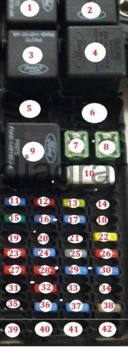
Identifying fuse panel.
Fuse box diagram.
fuses legend.
Fuse/relay location | Fuse amp rating | Passenger compartment fuse panel description |
1 | — | Accessory delay relay |
2 | — | Driver one touchdown relay |
3 | — | Blower motor relay |
4 | — | Flasher relay |
5 | — | Not used |
6 | — | Not used |
7 | 20A | Rear defrost relay coil feed |
8 | 40A | Blower motor |
9 | — | Rear defrost relay |
10 | 30A CB | Power seats, Delayed accessory |
11 | 10A | Right headlamp |
12 | 15A | High beam headlamps |
13 | — | Not used |
14 | — | Not used |
15 | 10A | Left headlamp |
16 | 10A | Not used (spare) |
17 | 15A | Stop lamp, Speed control deactivation switch |
18 | 15A | Park lamps, PWM (backlighting), Autolamps |
19 | 10A | Heated mirrors, Rear defrost switch indicator |
20 | 10A | Restraints (air bag module/OCS module) |
21 | 15A | Transmission range sensor (transmission position switch) |
22 | 15A | Front washer pump, Cluster (RUN/ACC), Integrated Control Panel (ICP) logic, Electrochromatic mirror |
23 | 30A | Front wiper motor |
24 | — | Not used |
25 | 20A | Power point |
26 | 20A | Power locks, Trunk release |
27 | 10A | Anti-lock Brake System (ABS), Speed control, Traction control, Brake-shift interlock, A/C function switch (manual A/C only), Temperature blend door (manual A/C only), Defrost coil |
28 | 15A | Turn signals, Back-up lamps |
29 | 20A | Cigar lighter |
30 | 10A | Courtesy lighting, Battery saver, Power mirrors, Decklid lamp, Glove box lamp |
31 | 10A | Blower motor relay coil, Electronic Automatic Temperature Control (EATC) logic |
32 | 10A | Cluster, Flex fuel module, ICP logic, Passive anti-theft module (GEM power), Compass |
33 | 15A | Hazard flasher, Cluster power, ICP power, EATC |
34 | 5A | GEM logic |
35 | 10A | Backlighting, Ashtray light |
36 | 2A | Powertrain Control Module (PCM) relay, Fuel pump relay, A/C clutch |
37 | 25A | Autolamp, Daytime Running Lamps (DRL), Flash-to-pass, Headlamp switch |
38 | 15A | Horn, Diagnostic connector (OBD II) |
39 | — | Not used |
40 | — | Not used |
41 | — | Not used |
42 | — | Not used |
CB – Circuit Breaker | ||
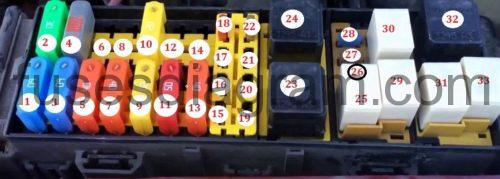
Power distribution box Ford Taurus.
The power distribution box is located in the engine compartment. The power distribution box contains high-current fuses that protect your vehicle’s main electrical systems from overloads.
Fuse box diagram ford taurus.
The high-current fuses are coded as follows.
Fuse/relay location | Fuse amp rating | Power distribution box description |
1 | 60A** | Fuse junction panel |
2 | 30A** | Powertrain Control Module (PCM) |
3 | 60A** | Fuse junction panel |
4 | 10A CB | Low speed cooling fan |
5 | 40A** | Cooling fan (main) |
6 | — | Not used |
7 | 40A** | Starter relay, Ignition switch |
8 | — | Not used |
9 | 20A** | Cooling fan (passenger side) |
10 | 20A** | Cooling fan (driver side) |
11 | 50A** | Rear defrost |
12 | — | Not used |
13 | 40A** | Anti-lock Brake System (ABS) module pump feed |
14 | — | Not used |
15 | 20A* | ABS module valve solenoid |
16 | 20A* | Fuel pump relay |
17 | 20A* | CD |
18 | 10A* | A/C clutch relay, PCM keep alive power |
19 | — | Not used |
20 | — | Not used |
21 | — | Not used |
22 | 5A* | Heated PCV valve |
23 | — | Starter motor relay |
24 | — | Fan relay |
25 | — | Wiper speed relay |
26 | 10A* | Alternator |
27 | 5A* | Rear control unit |
28 | 15A* | HEGO sensor, Transmission shift solenoid, A/C clutch relay, Canister vent |
29 | — | Wiper park relay |
30 | — | Fuel pump relay |
31 | — | PCM power relay |
32 | — | Fan relay |
33 | — | A/C clutch relay |
* – Mini Fuses ** – Maxi Fuses CB – Circuit breaker | ||

